Function Blocks
DI Function Block
Revision 11 HC900 Hybrid Control Designer Function Block Reference Guide 137
2/07
Configuration parameters
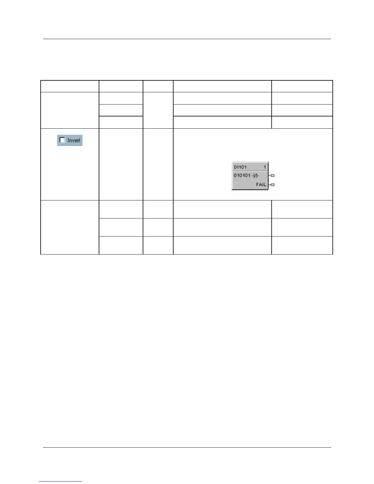
Table 42 Digital input configuration parameters
Properties Group Parameter Index # Parameter Description Value or Selection
Address Rack
0
Rack on selected I/O Module From 1 to 5
I/O Module
Address of select I/O Module From 1 to 12
Channel
Channel on selected I/O Module From 1 to 16 or 32.
1
If INVERT is selected, OUT = inverse of physical input.
The slash will be present in the CONTACT symbol only when
the invert box is selected on the dialog box. (See below.)
Failsafe Failsafe ON
N/A
set the output of the block to OFF
when failure is detected
Click on radio button
to select
Failsafe OFF
N/A
set the output of the block to ON
when failure is detected
Click on radio button
to select
Failsafe
HOLD
N/A
hold the output at the last value just
prior to the failure being detected
Click on radio button
to select

 Loading...


