Function Blocks
ROC Rate of Change Function Block
324 HC900 Hybrid Control Designer Function Block Reference Guide Revision 11
2/07
Example
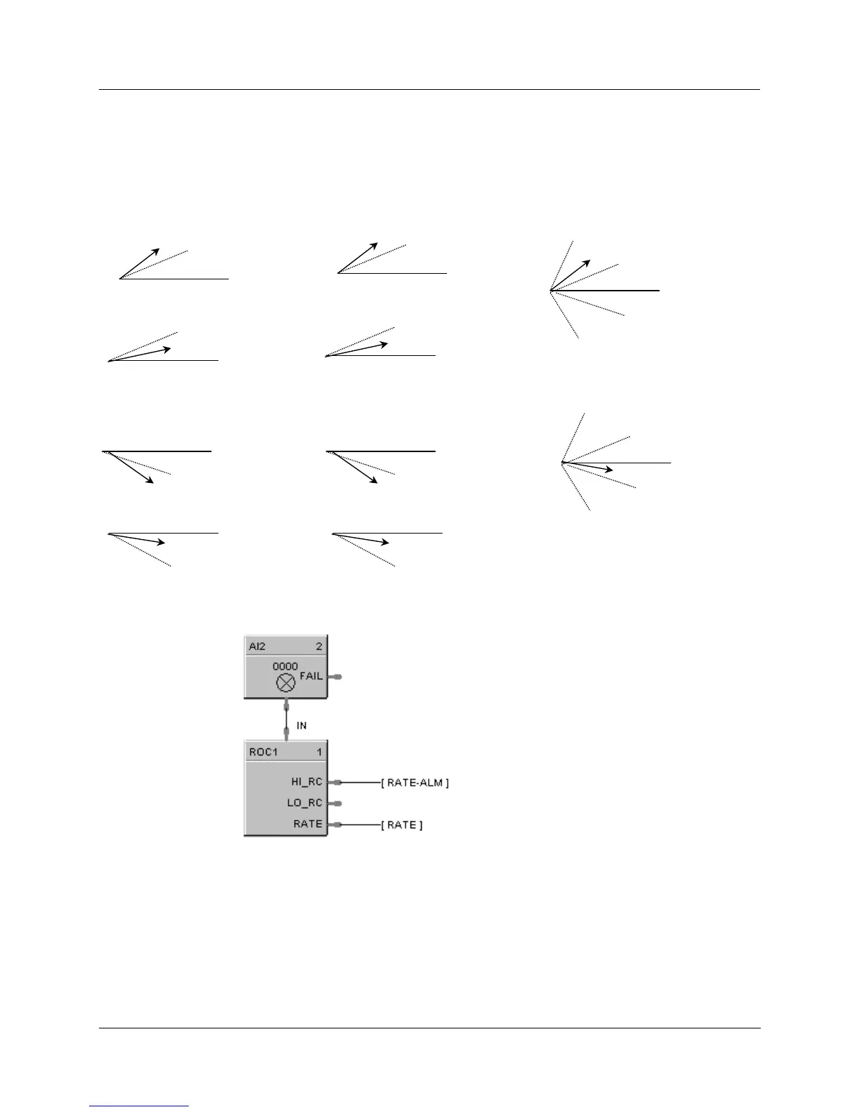
HFigure 86 illustrates various responses for the Rate Of Change Function Block. You can also use the ROC
block to alarm if Rate exceeds the Preset Setpoint Limit.
HI rate SP (INC)
HI RC = ON
HI rate SP (INC)
HI RC = OFF
HI rate SP (DEC)
HI RC = ON
HI rate SP (DEC)
HI RC = OFF
LO rate SP (INC)
LO RC = OFF
LO rate SP (INC)
LO RC = ON
LO rate SP (DEC)
LO RC = OFF
LO rate SP (DEC)
LO RC = ON
High Rate SP (INC ) LOW Rate SP (INC)
HI rate SP (INC)
HI RC = OFF
HI rate SP (DEC)
High/Low Rate SP (Both)
LO rate SP (DEC)
High Rate SP (DEC ) LOW Rate SP (DEC)
LO rate SP (INC)
LO RC = OFF
HI rate SP (INC)
HI RC = OFF
HI rate SP (DEC)
LO rate SP (DEC)
LO rate SP (INC)
LO RC = ON
Figure 86 ROC function block responses
Place in Alarm group for
Alarm detection/annunciation
Place in Overview Display
group to view rate
Signal Tags
Figure 87 ROC function block example

 Loading...


