Function Blocks
DSW Digital Switch Function Block
152 HC900 Hybrid Control Designer Function Block Reference Guide Revision 11
2/07
DSW Digital Switch Function Block
Description
The DSW label stands for Digital Switch.
This block is part of the
Logic and Fast Logic categories.
Function
Sets the output of the block equal to either input A or Input B depending on the value of input SA. If input
SA (Select A) is ON, then OUT = Input A, otherwise OUT = Input B.
Input
A
= 1
st
of two inputs to select from.
B = 2
nd
of two inputs to select from.
SA = Select A
Output
Out
= If SA is ON, then A, else B.
Block properties
Double click on the function block to access the function block properties dialog box.
Example
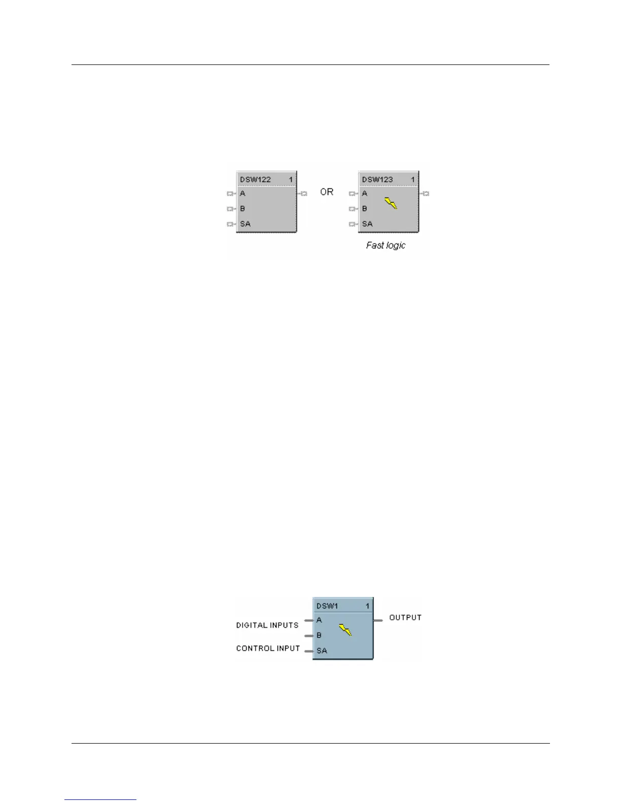
HFigure 35 shows an example of a DSW function block. The output is switched between two digital
inputs
based on the ON or OFF state of the control input. Output = A input state when SA input is OFF
and B input state when SA input is ON.
Figure 35 DSW function block example

 Loading...


