Function Blocks
PB Pushbutton Function Block
Revision 11 HC900 Hybrid Control Designer Function Block Reference Guide 251
2/07
Configuration procedure
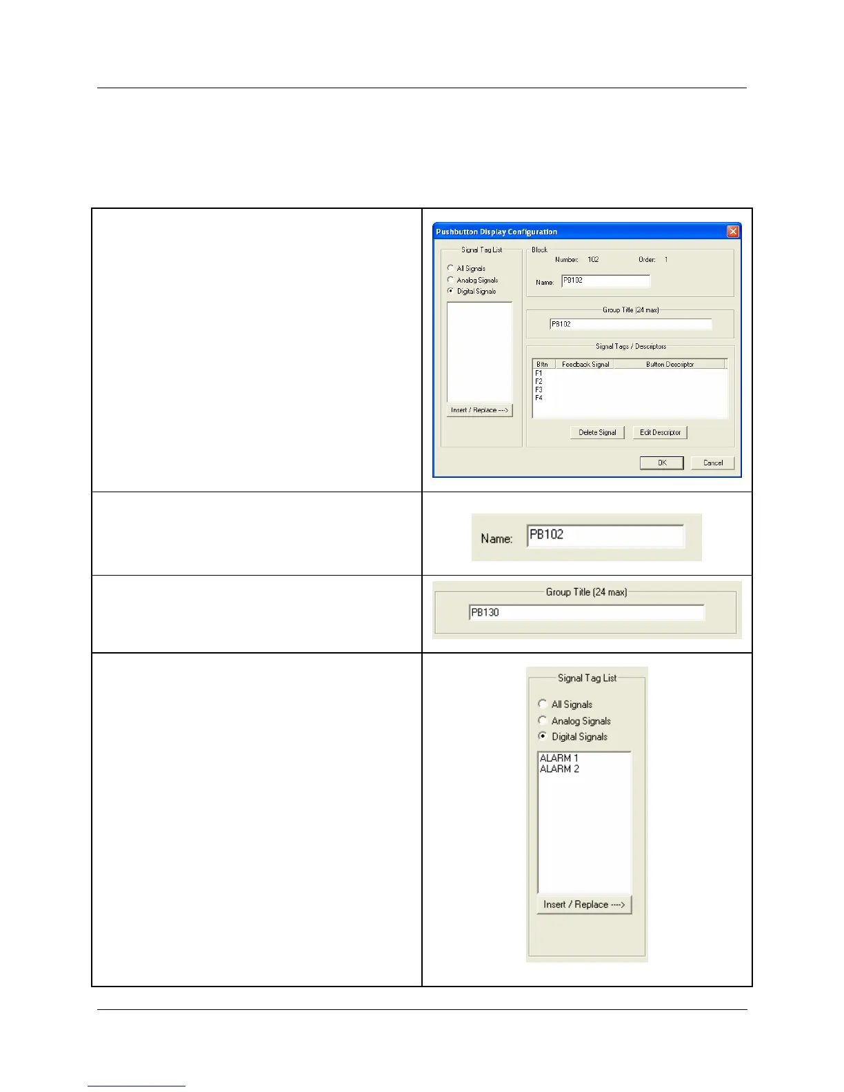
Follow the procedure in HTable 73 to configure the Pushbutton Function Groups.
Table 73 Pushbutton function group configuration
• There are four pushbuttons that can be configured for
each block.
You can assign just a label for the display using the
Output descriptor.
You can also select signal tags from the “Signal Tag
List” if you require a feedback signal to be shown on the
pushbutton display.
• Enter the Tag Name Text in the appropriate field.
• Enter the Group Title Text in the appropriate field.
The “Signal Tag List” field shows all the Signal Tags that
have been configured on the Function Block Diagram.
Select “All Signals”, ”Analog Signals”, or “Digital
Signals”.
• To Add a Digital Signal tag to a Pushbutton
location:
Click on a signal tag in the list, then click on
“Insert/Replace”. The selected Signal tag will be
placed in the next available position in the “Signal
Tags/Descriptors” field.
• To Insert a Digital Signal tag to a Pushbutton
location:
Select a position in the “Signal Tags/Descriptors”
field., then click on INSERT. (You must click in the
first column of the Selected Signal Tag list to select a
row.) The selected Signal tag will be placed in the
position chosen, and other signal tags will move
down as required. You may only insert to the
occupied portion of the list. An attempt to insert to
any empty row will place the new item in the first
empty row.

 Loading...


