Function Blocks
ONDT On Delay Timer Function Block
Revision 11 HC900 Hybrid Control Designer Function Block Reference Guide 227
2/07
Example
HFigure 61 shows a Function Block Diagram using an ONDT function block.
Start
Stop
DO 1
DO 1
DO 1
ON Timer
1
20 SEC
DO 2
On Lamp
SOL 4
SOL 5
DO 3
ON Timer
2
300 SEC
DO 2
CR1
CR1
DO 2
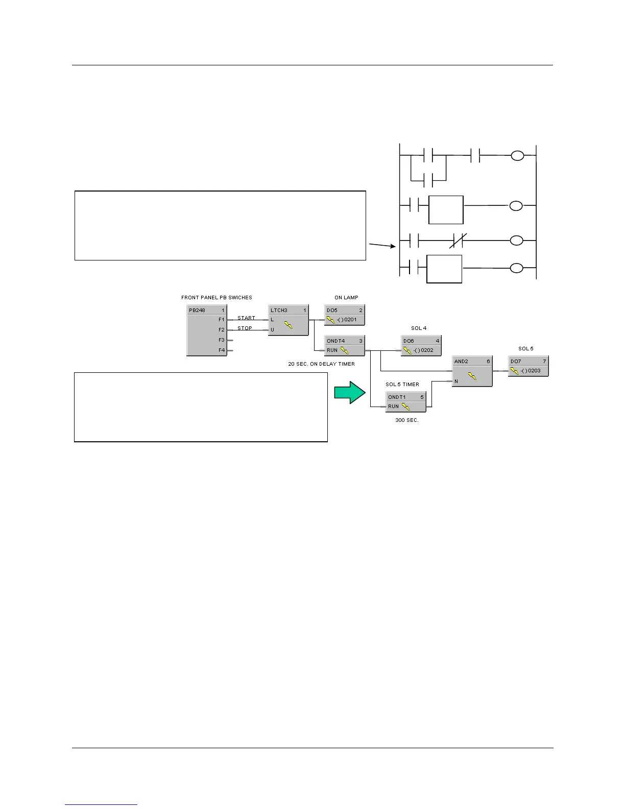
The application requirement is to turn on a pump, a compressor, etc. for
a fixed period of time - a common use for timers. This application, the
turn on of Pump2 for 300 sec., requires two additional rungs of ladder
logic. After SOL4 is turned ON, SOL 5 (Pump 2) is also turned ON
since CR1 (NC) is OFF (logic true). When ON Delay Timer 2 times out
after 300 sec., the CR1 coil is turned ON which turns off SOL 5.
PLC Ladder Logic
HC900 Logic
In HC900 logic, the output of ONDT4 timer activates
ONDT1 timer directly and is also an input for a 2-IN AND
gate, whose output activates the DO for SOL5. After ONDT1
times for 300 sec., its output turns ON, disabling the AND
gate output which de-energizes the DO. Three (3) additional
function blocks are used.
Figure 61 ONDT function block example

 Loading...


