Function Blocks
8DI Function Block
140 HC900 Hybrid Control Designer Function Block Reference Guide Revision 11
2/07
Block properties
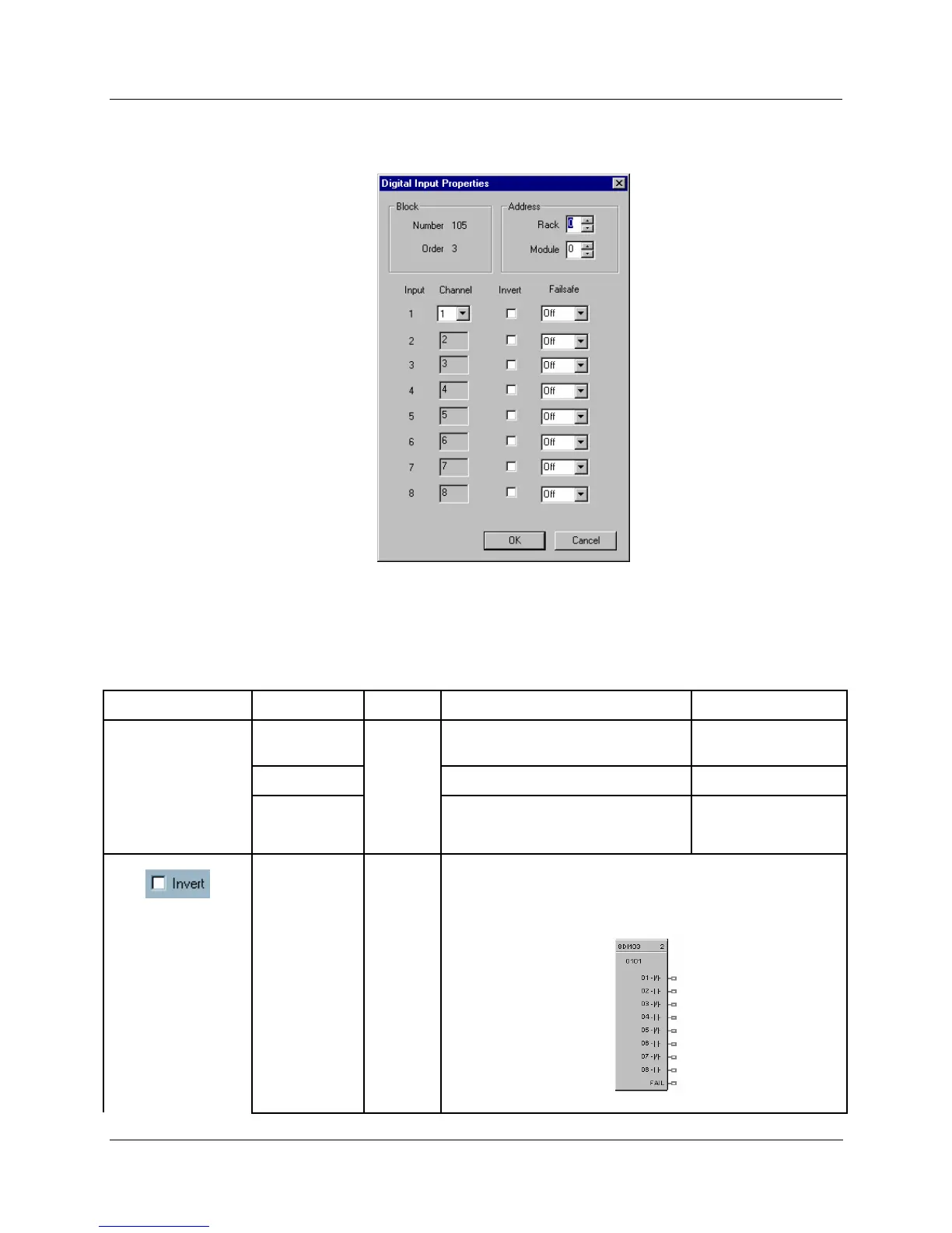
Double click on the function block to access the function block properties dialog box.
Configuration parameters
Table 43 Eight Digital input configuration parameters
Properties Group Parameter Index # Parameter Description Value or Selection
Rack
Rack Address of selected I/O
Module
From 1 to 5
Input 1 through
Input 8
I/O Module
0
Address of selected I/O Module From 1 to 12
Channel
Channel on selected I/O Module
1 to 8, 9 to 16, 17 to
24, 25 to 32
1
If INVERT is selected, OUT = inverse of physical input.
The slash will be present in the CONTACT symbol only when
the invert box is selected on the dialog box. (See below.)

 Loading...


