EasyManuals Logo

Honeywell HC900 Reference Guide

Honeywell HC900
456 pages
To Next Page IconTo Next Page
To Previous Page IconTo Previous Page
Page #276 background imageLoading...
Page #276 background image
Function Blocks
PDW Peer Data Write Function Block
262 HC900 Hybrid Control Designer Function Block Reference Guide Revision 11
2/07
Configuration Parameters
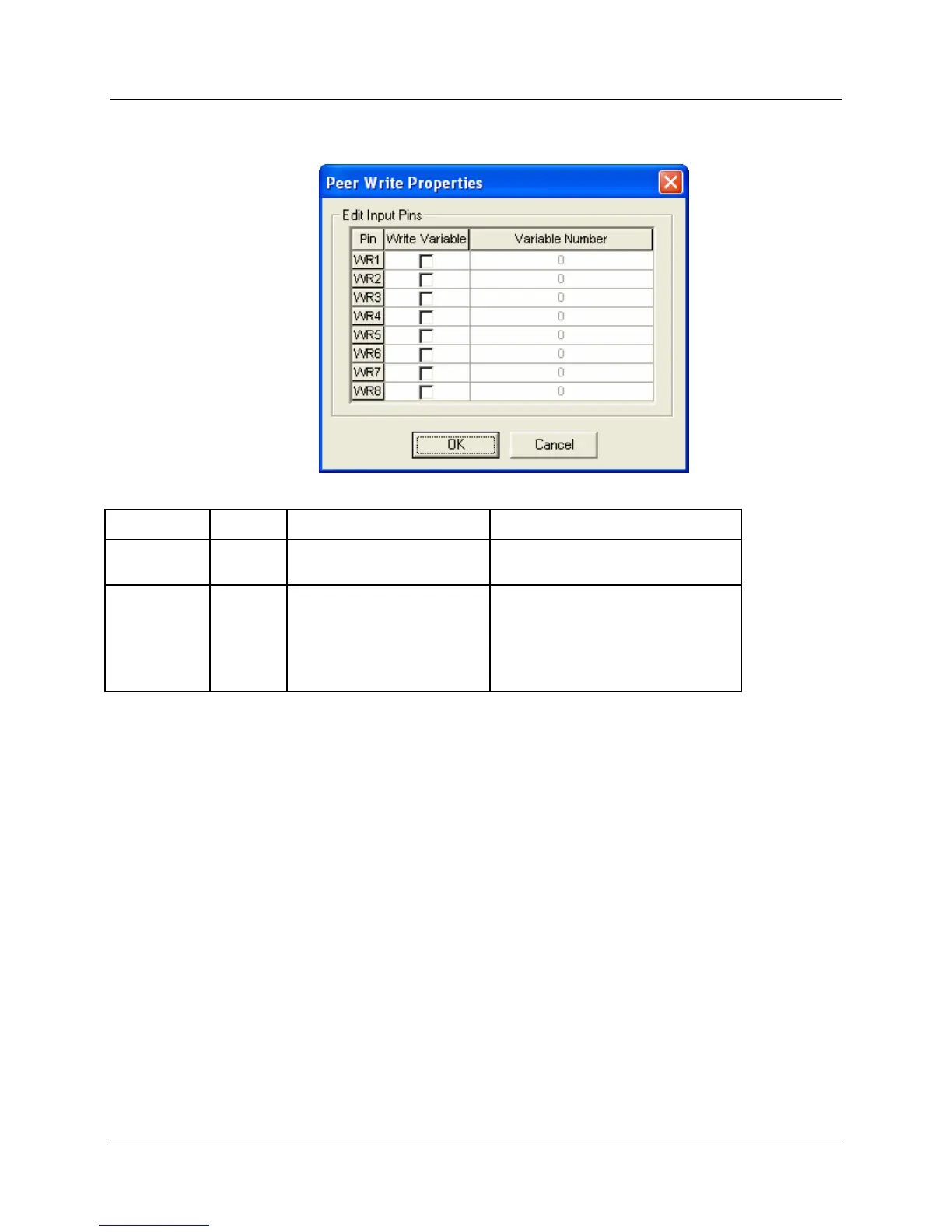
Edit Input Pins
Parameter Index # Parameter Description Value or Selection
Write
Variable
N/A
Activates the WR1 through
WR8 pins for writes.
Click on selection box next to the pin
number.
Variable
Number
N/A
Variable number that
appears on the Tag
Information Report.
See "Tag Information
Example".
Enter a variable number from the
report.
You can also use the "Find a
Signal tag" procedure to find the
variable number.

Table of Contents

Other manuals for Honeywell HC900

Questions and Answers:

Question and Answer IconNeed help?

Do you have a question about the Honeywell HC900 and is the answer not in the manual?

Honeywell HC900 Specifications

General IconGeneral
SeriesHC900
RedundancyOptional
Programming LanguageFunction Block Diagram, Ladder Logic, Structured Text
InputsAnalog, Digital
OutputsAnalog, Digital, Relay
DisplayOptional
ControlPID, Advanced Control
Power Supply24V DC or 100-240V AC
Storage Temperature-40°C to 85°C
Humidity5% to 95% non-condensing
Communication ProtocolsModbus, Ethernet

Related product manuals