EasyManuals Logo

Honeywell HC900 Reference Guide

Honeywell HC900
456 pages
To Next Page IconTo Next Page
To Previous Page IconTo Previous Page
Page #400 background imageLoading...
Page #400 background image
Function Blocks
TCPR Function Block
386 HC900 Hybrid Control Designer Function Block Reference Guide Revision 11
2/07
Sequence
Number
Parameter
Field
Action Selections Comments
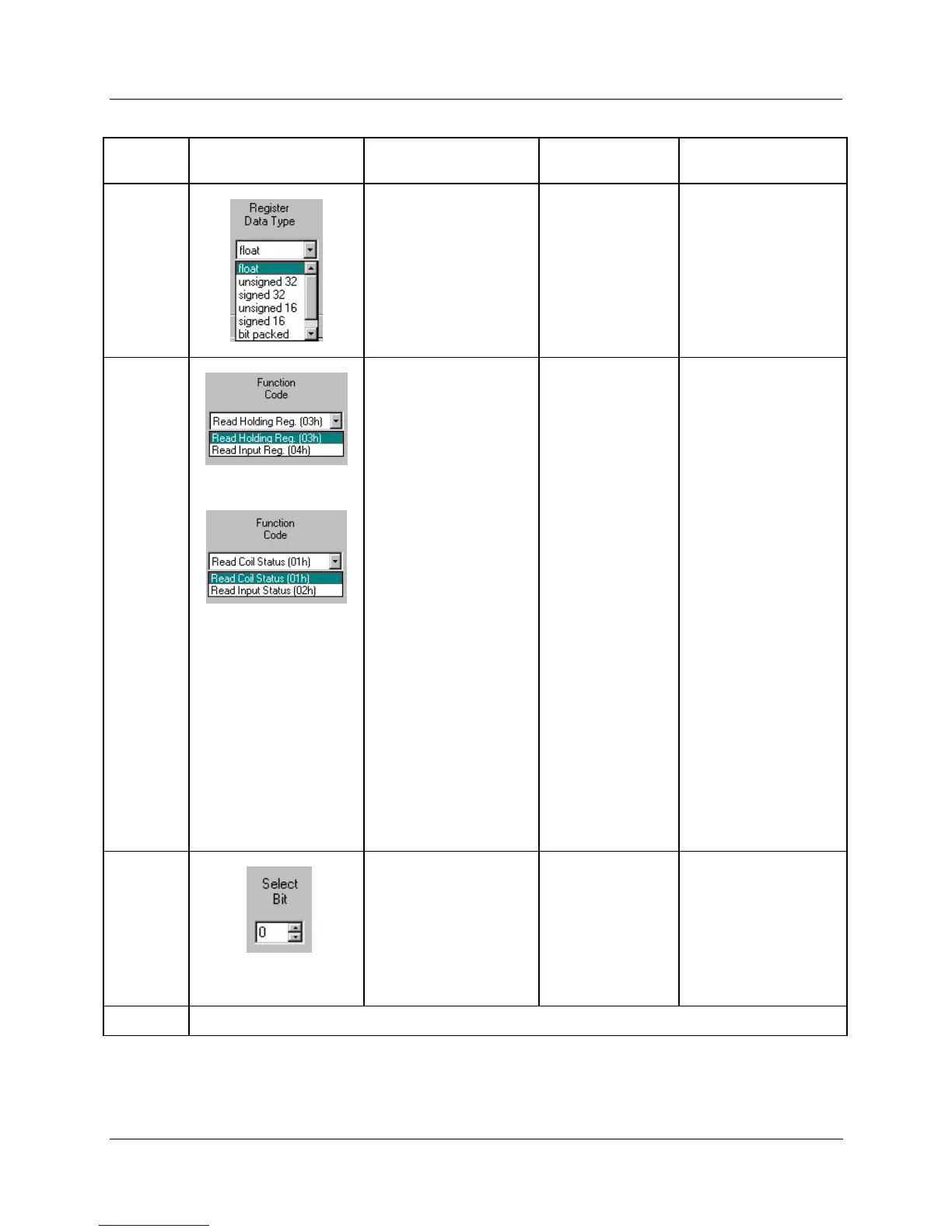
4
From the drop down
menu, select the
Register Data Type
Float
Unsigned 32
Signed 32
Unsigned 16
Signed 16
Bit Packed
Single Bit
If read as an integer,
the output is converted
to a floating point.
5
Select a function code
for
“Float, Unsigned,
Signed, or Bit Packed”
register data type
Read Holding
Reg – Function
Code 03
Read Input
Registers –
Function Code
04
Function code 03 or
Function code 04 is
used to read the
contents of input
registers in the slave.
Select a function code
for
“Single Bit”
Register data type.
Read Coil
Status –
Function Code
01
Read Input
Status –
Function Code
02
Function code 01 is
used to read a slave's
coil's (discrete output's)
ON/OFF status of the
slave device in a binary
data format.
Function code 02 is
used to read a slave's
input's (discrete
input's) ON/OFF status
of the slave device in a
binary data format.
Output is floating point
equivalent (0.0 or 1.0).
NOTE: Refer to the
Communications
manual for the function
codes supported by the
specific device.
6
Select which bit (0-15)
to read when Register
Data Type = Bit Packed
0 to 15
If read as a bit packed
number, you must
select which bit to
mask (0-15).
The output will be the
floating-point
equivalent (0.0 or 1.0)
of the masked bit.
7
You must press [APPLY] to accept the register changes.

Table of Contents

Other manuals for Honeywell HC900

Questions and Answers:

Question and Answer IconNeed help?

Do you have a question about the Honeywell HC900 and is the answer not in the manual?

Honeywell HC900 Specifications

General IconGeneral
SeriesHC900
RedundancyOptional
Programming LanguageFunction Block Diagram, Ladder Logic, Structured Text
InputsAnalog, Digital
OutputsAnalog, Digital, Relay
DisplayOptional
ControlPID, Advanced Control
Power Supply24V DC or 100-240V AC
Storage Temperature-40°C to 85°C
Humidity5% to 95% non-condensing
Communication ProtocolsModbus, Ethernet

Related product manuals