3. Operation of CON Related Controllers
133
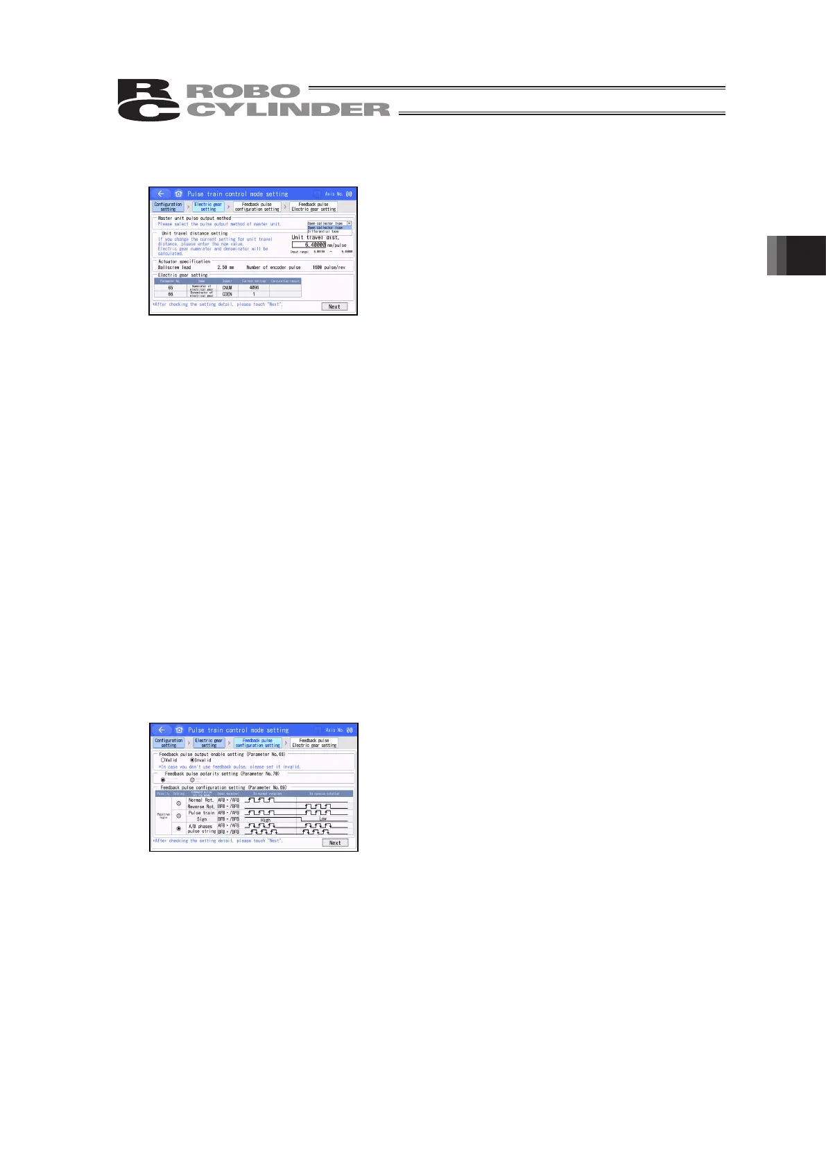
3.23.2 [Electric gear setting]
Second, display the [Electric gear setting] screen.
Once setting is finished, touch [Next] button.
[Contents of Display]
Master unit pulse output method Select the pulse output system of the host unit whether it is
the open collector type or differential (line drive) type.
Unit travel distance setting Set the unit movement amount of the actuator for one pulse.
With this input value, the numerator and the denominator of
the electronic gear are automatically figured out. In case the
value is out of the input range as a result of calculation, an
error message will be displayed in red. Change the value.
Actuator specification The ball screw lead and the number of encoder pulses of
the actuator are displayed.
Electronic gear setting It is a parameter to determine the unit movement amount of
the actuator for one pulse of the command pulse train input.
Input the unit movement amount and this parameter can be
automatically figured out and the set numbers for the
numerator and the denominator of the electronic gear get
displayed.
Electronic Gear Numerator (Parameter No. 65)
Electronic Gear Denominator (Parameter No. 66)
3.23.3 [Feedback pulse configuration setting]
Third, display the [Feedback pulse configuration setting]
screen.
Once setting is finished, touch [Next] button.
[Contents of Display]
Feedback pulse output enable setting Set the validation of the feedback pulse output.
(Parameter No. 68)
When the feedback pulse output is “valid”, conduct the following settings.
Feedback pulse polarity setting Set the feedback pulse whether active high or active
low. (Parameter No. 70)
Feedback pulse configuration Setting Set the format for the feedback pulse output.
(Parameter No. 69)
 Loading...