3. Operation of CON Related Controllers
143
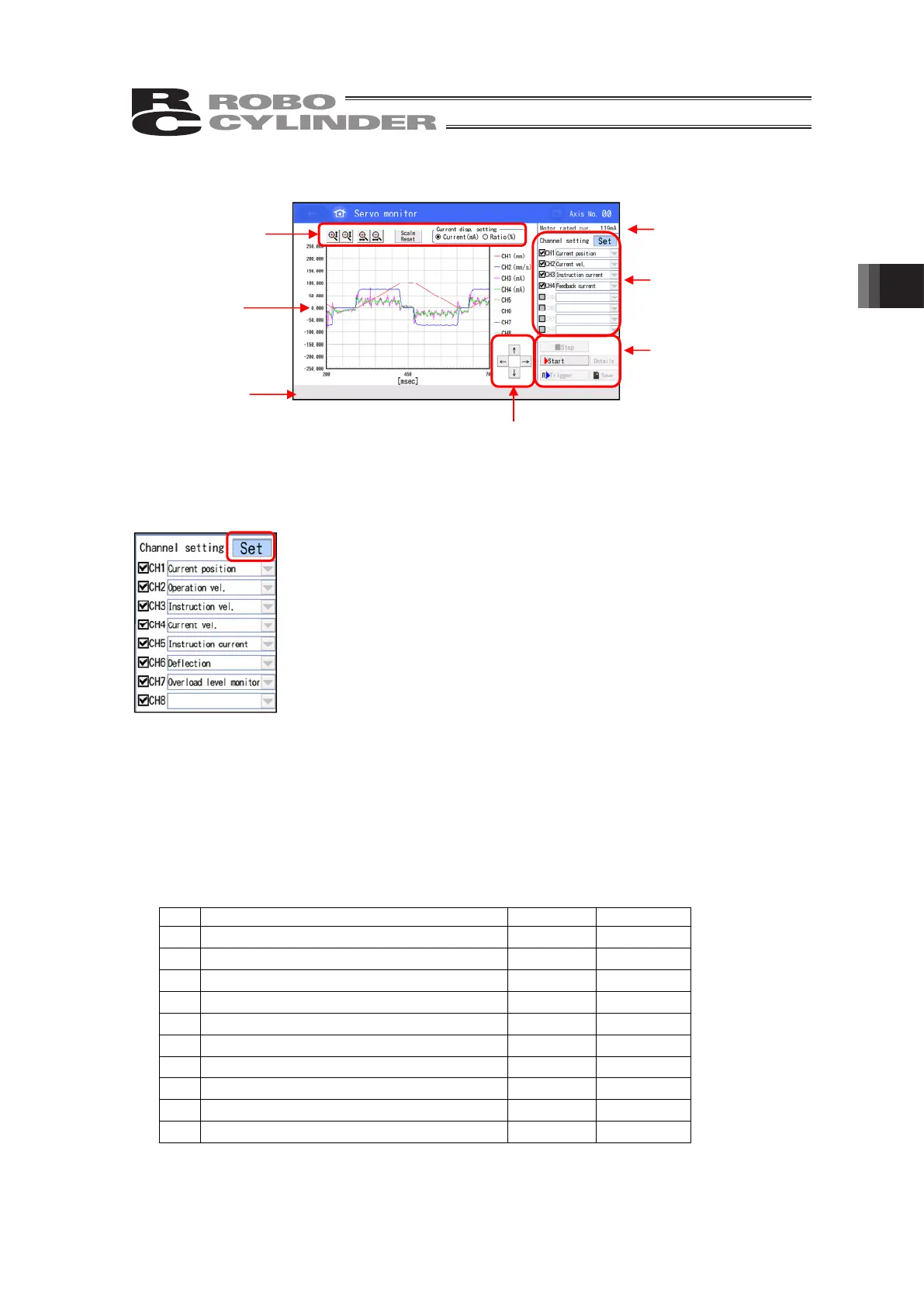
3.25.1 Servo Monitor (Waveform Display) Screen
3.25.1.1 Channel Settings
Select an item to be monitored in channel settings.
Select an item to be monitored from the select menu in each channel.
Once selection is made, touch [Confirm] button to set it to monitoring standby
status.
■ Checkmarks in the Left of Items
Items with a checkmark on can show the waveform in the screen.
For the items with no checkmark, the waveform will not be shown, but the
data is acquired.
■ About Number of Channels
For the number of channels, selection can be made from 2, 4 and 8 (4 and 8 for SCON-CA).
Number of channels can be set in Parameter No. 112 “Monitoring Mode Select”.
[Reference] (Note) It differs depending on models.
•
Number of channels when No. 112 is 1 = 4
•
Number of channels when No. 112 is 2 = 8
•
Number of channels when No. 112 is 3 = 2
The monitor items are shown in the table below.
(Note) Items subject to monitoring differ depending on models.
Item name Units Unit
(Note 1)
1) Current Position [mm] ←
2) Velocity Operation Amount [mm/s] ←
3) Velocity Actual Command Value [mm/s] ←
4) Current Velocity [mm/s] ←
5) Command Current [mA] [%]
6) Feedback Current [mA] [%]
7) Current Load (for SCON-CA/CB only) [N] ←
8) Deviation [Pls] ←
9) Command Pulse Counter [Pls] ←
10) Overload Level Monitor [%] ←
Note 1 : Unit when rated ratio display selected
Channel Settings
(Refer to 3.25.1.1)
Monitor Operation
Buttons
(Refer to 3.25.1.3)
Display Setting
Buttons
(Refer to 3.25.1.2)
Display Setting Buttons (Refer to 3.25.1.2)
Waveform
Display Area
Other Displays
(Refer to 3.25.1.4)
Other Displays
(Refer to 3.25.1.4)
 Loading...