3. Operation of CON Related Controllers
70
Zone output signal
Zone output signal
Zone output signal
Home
Backward
end
Forward
end
Midway
poin
(7) Incremental
Specify absolute coordinates or incremental coordinates.
The factory setting is 0.
0: Absolute coordinate specification
1: Incremental coordinate specification
Warning: Be sure to specify absolute coordinates on PCON-C/CF/CA/CFA/CB,
ACON-C/CA/CB, DCON-CA/CB, SCON-C/CA/CAL/CB, ROBONET, ERC3 PIO
Converter, RCP6S, MCON and MSCON (Remote I/O mode) controllers of
solenoid valve mode 2, or PCON-CY/CYB, ACON-CY/CYB and DCON-CYB
controllers of solenoid valve mode 1. (same for Safety Category Complied Type)
(Note) If incremental coordinates are specified on these controllers, a position
data error occurs.
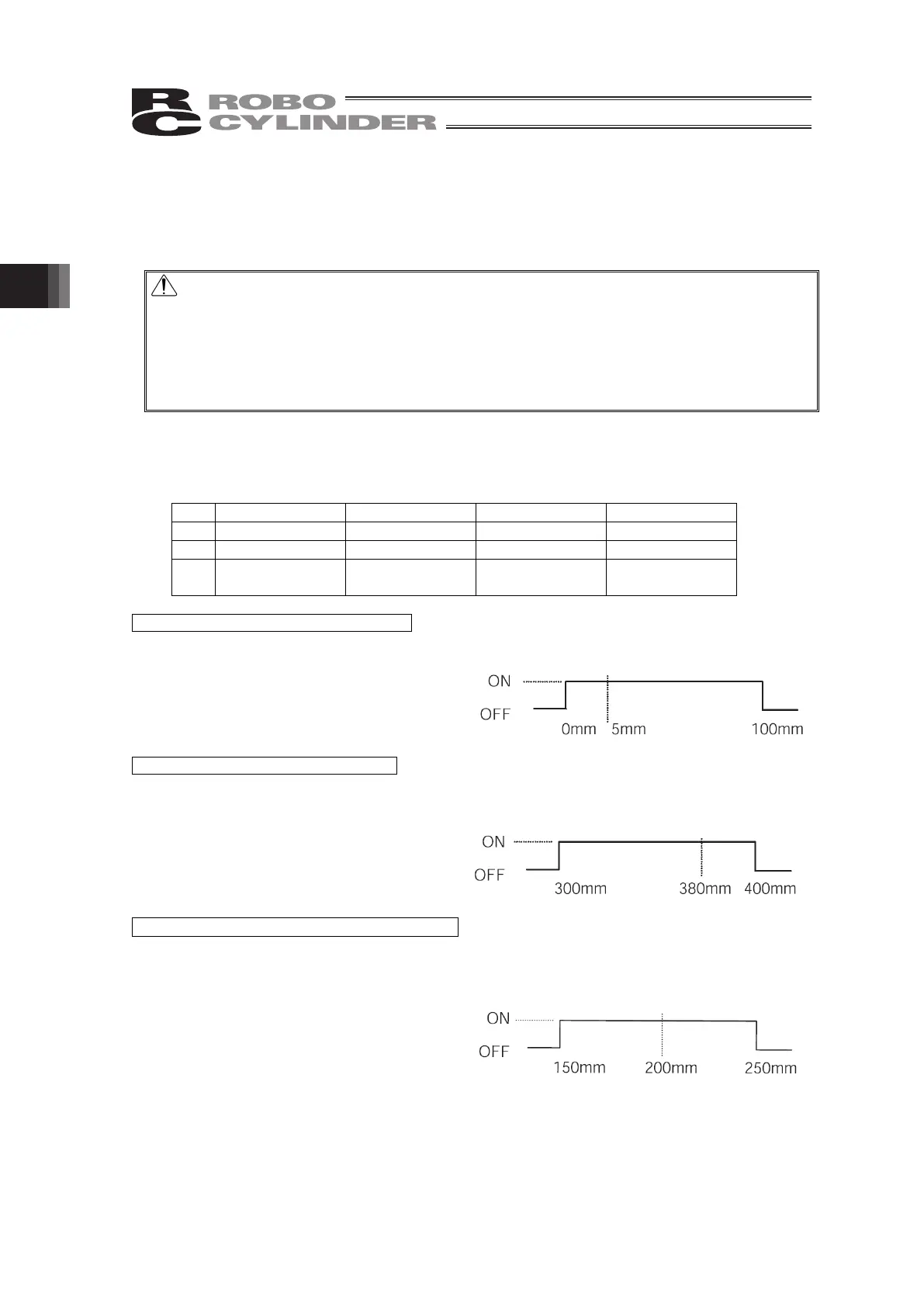
(8) Zone +/- [mm]
Define, for the standard type, the zone in which the zone output signal turns ON.
These parameters can be set differently for each target position.
[Setting example]
No. Position [mm] Zone + [mm] Zone - [mm] Remarks
0 5.00 100.00 0.00 Backward end
1 380.00 400.00 300.00 Forward end
2 200.00 250.00 150.00
Intermediate
position
Movement command to backward end
Movement command to forward end
Movement command to intermediate position
(9) Threshold [%]
With SCON-CA/CAL/CB, PCON-CF/CFA controllers, a load output signal (PIO) is output if the
command torque exceeds the value (%) set in "Threshold" inside the verification range.
The verification range is set by “Zone+/Zone-.”
It is used to determine if press-fitting action was performed successfully.
* For details, refer to the instruction manual for your SCON-CA/CAL/CB,
PCON-C/CF/CA/CFA/CB/CFB controller. (same for Safety Category Complied Type)
 Loading...