8.11.3.4 Setting the switching point and switching differential
1. Use «Up» or «Down» to select the
SP
line.
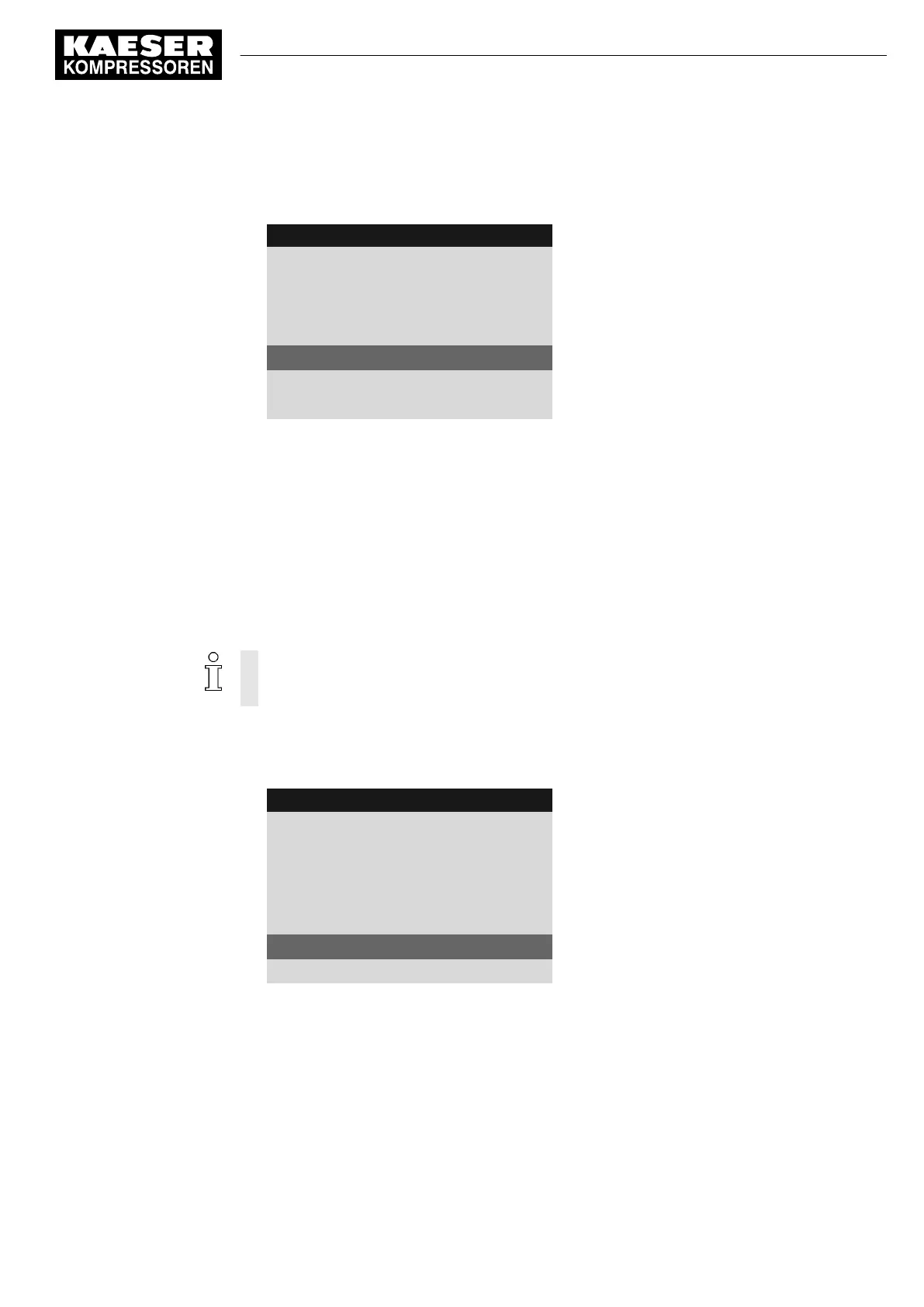
8 8 p s i 0 8 : 1 5 A M 1 7 6 ° F
Header
5.7.2.1.1 AnMod_p_1
Menu
AnMod_p_1 Title 0.0 psi
Message text
pNloc ☑
Selected analog measured value, activated
·········
SP: 116psi ¦ SD: −7.3psi
Switching point (SP) and switching differential (SD)
td: 0s
Time delay (td)
·········
2. Press «Enter».
The display for the current value of the switching point flashes.
3. Use «Up» or «Down» to set the
SP
value.
4. Press «Enter».
The setting is applied.
5. If necessary, adjust the value for SD in the same manner.
Result The threshold value for the SP switching point and the SD switching differential are set.
8.11.3.5 Setting the time delay
The delay can be set between 0 and 600 seconds. The delay is counted down from 600 in 1
second increments with the «DOWN» key and counted upwards from 0 (zero) in 1 second
increments with the «UP» key.
1. Use «Up» or «Down» to select the
td
line.
2. Press «Enter».
The
td
delay time flashes.
8 8 p s i 0 8 : 1 5 A M 1 7 6 ° F
Header
5.7.2.1.1 AnMod_p_1
Menu
AnMod_p_1 Title 0.0 psi
Message text
pNloc ☑
Selected analog measured value, activated
·········
SP: 116psi ¦ SD: −7.3psi
Switching point (SP) and switching differential (SD)
td: 0s
Time delay (td)
·········
3. Use «Up» or «Down» to set the time delay in seconds.
4. Press «Enter».
Result The
td
delay time has been set.
8.11.3.6 Setting the message type
1. Select the message type line with the «Up» and «Down» keys.
8 Initial Start-up
8.11 Setting input and output signals
No.: 9_9450 13 USE
User Manual Controller
SIGMA CONTROL 2 SCREW FLUID ≥5.1.2
161

 Loading...