Keysight N9915-90020 User’s Guide 215
SA (Spectrum Analyzer) Mode (Option 233–Mixed Analyzers)FUTURE
SA Mode Settings
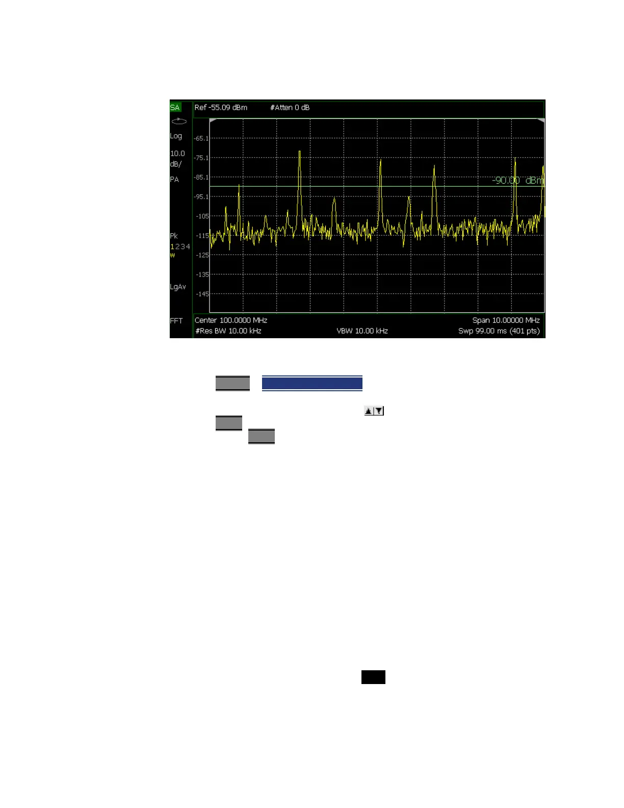
Figure 9-18 Display Line with Annotations
How to create and move a Display Line
1. Press Limit 8
> Display Line OFF ON
2. Then enter a Y-axis value using the arrows or the rotary knob, then
press Enter
. Or enter a value using the numeric keypad and press a suffix
key or press Enter
.
Learn more,
“All about Limit Lines” on page 749.
Noise Marker
For comparison purposes, electronic noise measurements are often displayed
as though the measurement was made in a 1 Hz Res BW. However, making an
actual measurement at a 1 Hz Res BW is extremely slow.
A Noise Marker, unique to SA Mode, mathematically calculates the noise
measurement as though it were made using a 1 Hz bandwidth.
Several data points (or ‘buckets’) are averaged together to calculate the Noise
Marker readout. To accurately measure noise, the Noise Marker should NOT be
placed on, or too close to, a signal. The distance from a signal depends on
several factors. To know if an accurate reading is being made, move the Noise
Marker until consistent measurements are displayed in adjacent data points.
In addition, when a Noise Marker is displayed, the Detection method is
automatically switched to Average and PAvg is shown on the FieldFox screen.
This occurs only when Detector is set to Auto. Learn more in “Detection
Method” on page 213
.