626 Keysight N9915-90020 User’s Guide
ERTA (Extended Range Transmission Analysis) Mode - Option 209
Start Connection Wizard
—Press Continue.
STEP 5: Measure Jumper Cables
These steps can be used to characterize an Input and Output jumper cable that
may be connect the DUT to the FieldFox. The loss of the characterized jumper
cables can then be removed from the DUT measurements. The measurements
are stored to the internal Cables folder using an auto-generated *.csv filename.
— The Input cable is attached between the Source/splitter output and the
DUT input.
— The Output cable is attached between the DUT output and the Receiver
unit.
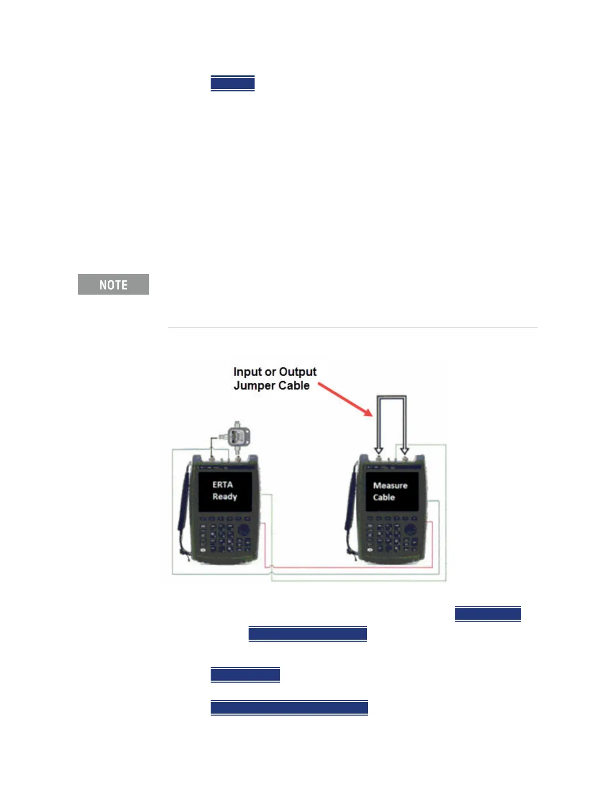
Figure 26-1 Input and Output jumper cables are measured on the Receiver unit
If your DUT input AND output is connected directly to the FieldFox, or you
choose to ignore the loss of BOTH jumper cables, then press
Skip this step.
Otherwise, press
Measure Jumper Cables.
Do the following for both the Input and Output jumper cables:
—Press
Skip this step to skip the cable measurement.
— Otherwise, connect the Input / Output jumper cable as shown below, then
press
Measure Input (or Output) Cable.
For optimum flexibility, use the Scale, then More, then Corrections menu to
measure, save, and recall cable characterizations. These softkeys are
duplicated from the SA Field Strength - Antenna/Cable characterization.
Learn more in
“Field Strength Measurements” on page 163.