Settings
172
Pos: 27.8.1 /BA/ Einstellungen/L adewagen/Sch neidwer k/Messerbalken justi eren @ 3\mod_1 20426879910 3_78.doc @ 7 0175
12.5 Adjusting the blade bar
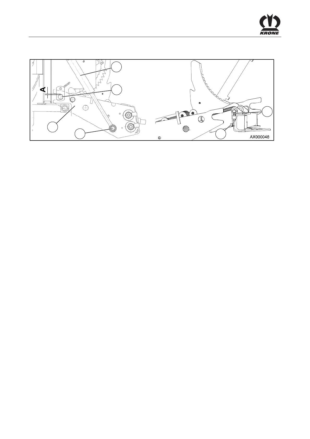
1
4
6
2
3
5
Figure 113:
The function of the blade bar during the swivelling-in should be adjusted in such a way that the
fork pieces (1) run over the bearing bolts (2) without touching them.
Due to high operational demands and setting of components on the blade bar, a readjustment
of the blade bar may be required.
In this case, the following work steps must be observed.
Pos: 27.8.2 /BA/ Einstellungen/L adewagen/H öheneinstellung der Gabelstüc ke @ 3\mod_1 20427500593 1_78.doc @ 7 0194
12.5.1 Height adjustment of the fork pieces on the right and left side of the machine
• Completely lower the blade bar via the control unit (maintenance position).
• Uncouple the left and right cylinder (4).
• By turning the screw (3) (right and left-hand side of the machine) on the swivel head,
adjust the fork pieces in such a way that dimension a = 2-3 mm between the fork piece
(1) and the bearing journal (2).
Pos: 27.8.3 /BA/ Einstellungen/L adewagen/N eigung des M esserbalkens ei nstellen @ 3\ mod_120427507 8431_78.doc @ 70291
12.6 Setting the inclination of the blade bar
• The two cylinders (4) of the cutting system must be completely extended.
• The fork pieces (1) of the blade bar must be swivelled all the way forward and be held in
this position.
• By means of the screws (5) on the swivel head, adjust the inclination angle of the cutting
system until the left cylinder (4) can be easily attached to the holding bolt (6).
Pos: 27.8.4 /BA/--- --Seitenumbruc h------ @ 0\ mod_1196175 311226_0.doc @ 4165