Maintenance
180
Pos: 31.14.8 /Üb erschriften/Üb erschriften 2/A-E/ Anpassen d es Hydrauliksyst ems @ 1\ mod_1201241743 588_78.doc @ 52013
13.7 Adjusting the hydraulic system
Pos: 31.14.9 /B A/Wartung/Lo ad-Sensing/Lade wagen/Bild Load-Sensing Ansc hluss AX @ 2\mod_12035 96775626_78.d oc @ 67033
AX000007
2 1
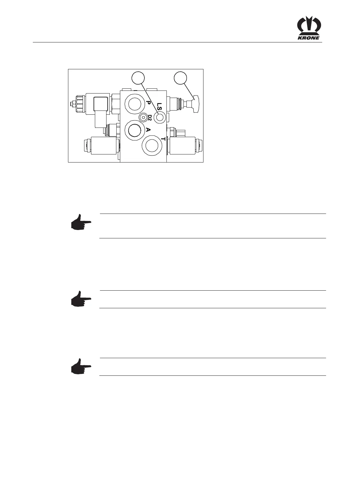
Figure 117:
Pos: 31.14.10 / BA/Wartung/L oad-Sensing/Lad ewagen/Anpass en des H ydrauliksystems La dewagen @ 0\ mod_119989 3777643_78.d oc @ 36822
The Comfort hydraulic system of the machine must be adjusted to the tractor It is designed for
continuous circulation. The adjustment is made by adjusting the hydraulic system screw (1) on
the electromagnetic valve block. The block is located on the front right of the wagon under the
protective box.
Note
The adjustment depends on the hydraulic system of the tractor and must be
made while there is no pressure in the loading wagon!
Unscrew the system screw (1) as far as it will go for:
• Tractor with an open (constant-current) hydraulic system (for additional information,
please refer to the tractor manufacturer's operating instructions)
• Tractors with LS pump and non-activated load-sensing system
Note
This adjustment is set when the unit leaves the factory.
Screw the system screw (1) as far as it will go for:
• Tractors with closed (constant pressure or load sensing) Hydraulic system (For more
information, please refer to the tractor manufacturer's operating instructions)
• Tractors with LS pump and message line that is connected
Note
The connection (2) for the message line is under the hydraulic system screw.
Pos: 31.14.11 / BA/-----Seiten umbruch------ @ 0\mod_11961 75311226_0.doc @ 4165