Commissioning
37
Pos: 12.17 /BA/Ers tinbetriebna hme/Ladewage n/Höheneinst ellung MX @ 3\ mod_12058546 94166_78.d oc @ 74015
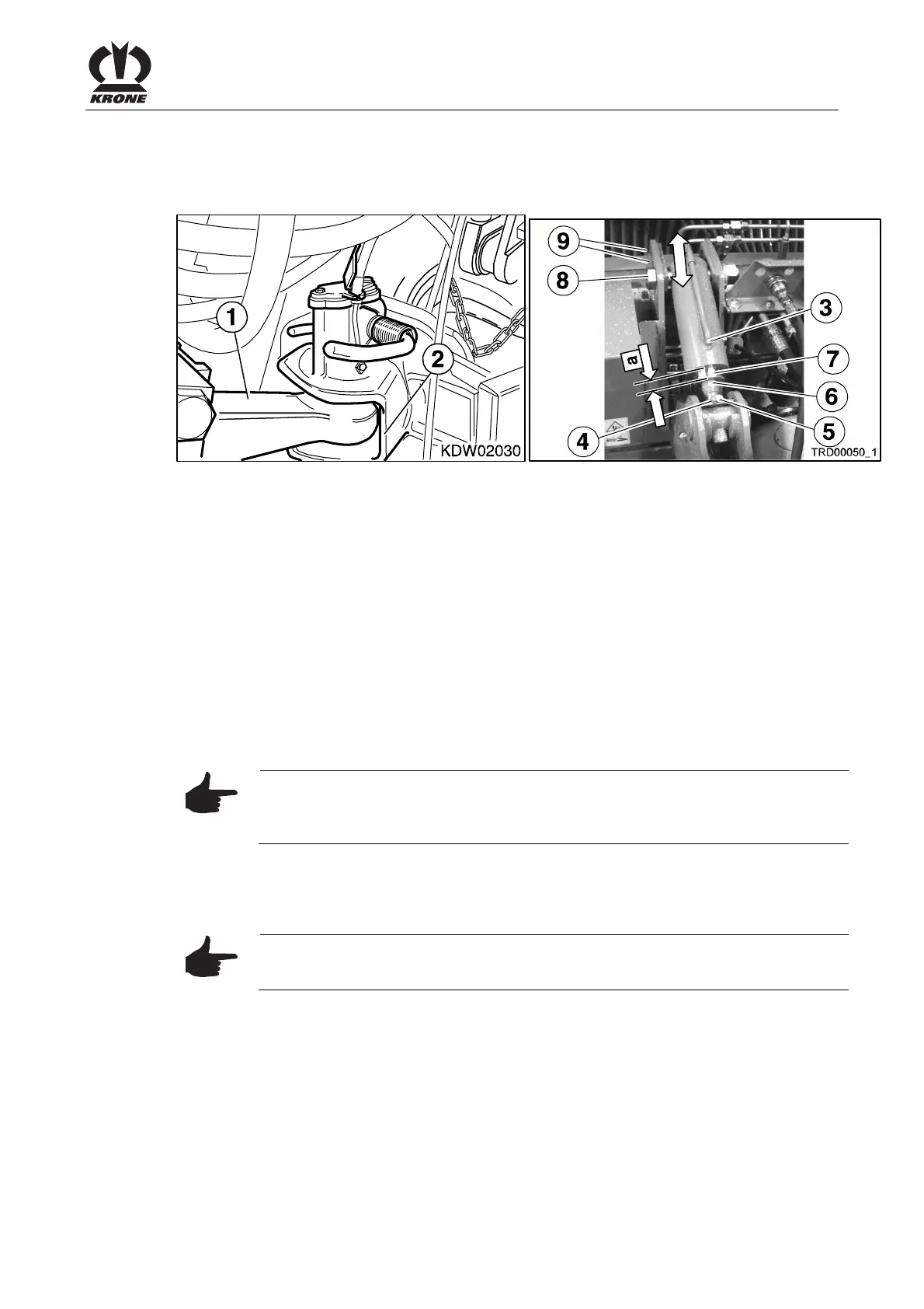
5.5 Height adjustment
5.5.1 Adjusting the Cylinders
Fig. 1• Hook the hitch (1) of the wagon into the hitch coupling (2) of the tractor.
• Move the offset drawbar to basic position, i.e.:
Without drawbar suspension:
• Retract cylinder (3) completely
With drawbar suspension (optional)
• Extend cylinder (3) 20 mm (measured on the plunger rod (7))
• Activate the offset drawbar until the frame height X=1.35- 1.40 m. (MX 310)
• Activate the offset drawbar until the frame height X=1.45- 1.50 m. (MX 350)
• Remeasure dimension "a" on the cylinder (3)
• Park the wagon on the parking jack.
• Loosen the nut (4).
• Remove the screw (5).
• Turn the threaded spindle (6) by the remeasured dimension "a" .
Note
The plunger (7) of the cylinder must not be completely inserted to the stop to
allow later adjustments.
• Screw the screw (5) back in.
• Lock the nut (4) in place again.
Note
The adjustment must be made evenly for both cylinders.
If necessary, change the position of the cylinder (3) and its fastening (8). Use one of the holes
(9) in the drawbar beam to do this.
Pos: 12.18 /BA/-- ---Seitenum bruch------ @ 0\m od_119617531 1226_0.doc @ 4165