Comfort Control Unit
76
Pos: 21.3.3 /BA/ Info-Center/Lad ewagen/Anba u @ 36\mod_12 60362759020 _78.doc @ 336 453
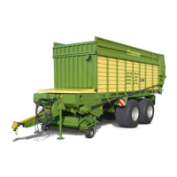
9.1 Mounting the control unit
2
ZX000027
1
3
ZX000029
Fig. 40
Direct fastening
• Fasten the retainer (1) using the drill holes (2) already present.
The control unit (3) is fixed by the magnetic plate (4) on the retainer (1).
Pos: 21.3.4 /BA/ Info-Center/Hi nweis Bedienei nheit muss pr oblemlos vo m Fahresitz aus bedi ent werden @ 36\mod_12 60363833832_7 8.doc @ 3364 74
Note
Install the control unit with the support (1) in that way, that the control unit can be operated from
driver´s seat without any problems.
Pos: 21.3.5 /Übersc hriften/Übersc hriften 2/P-T/ Spannungs versorgung @ 28 \mod_1250578 107003_78. doc @ 275490
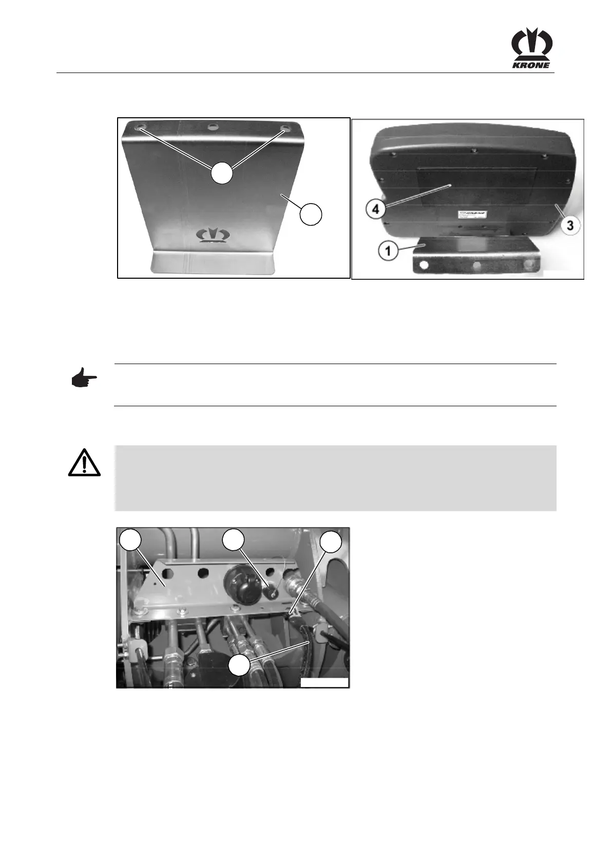
9.2 Electrical power supply
Pos: 21.3.6 /BA/ Sicherheit/Gef ahrenhinweise/ Ausfall der Be dieneinheit @ 6\ mod_121506 1997306_78.d oc @ 98196
Danger! - Failure of control unit
Effect: Danger to life, injuries or damage to the machine.
Make sure during assembly that the connection cables are not tight and that they do not come
in contact with the tractor wheels.
Pos: 21.3.7 /BA/ Info-Center/Lad ewagen/Span nungsversorgu ng @ 28\mod_ 12505787095 03_78.doc @ 275515
L400450_1
4
1
5
6
Fig. 41
Connect the power supply cable (1) (12 V) to the power socket (DIN 9680) on the tractor and
machine. The socket (5) on the machine side is on the front metal cover (6).
Pos: 21.3.8 /BA/ Info-Center/Lad ewagen/Anba u Bedieneinheit @ 0\mod_1 20063720177 1_78.doc @ 458 34