Gocator Line Profile Sensors: User Manual
Gocator Web Interface • 213
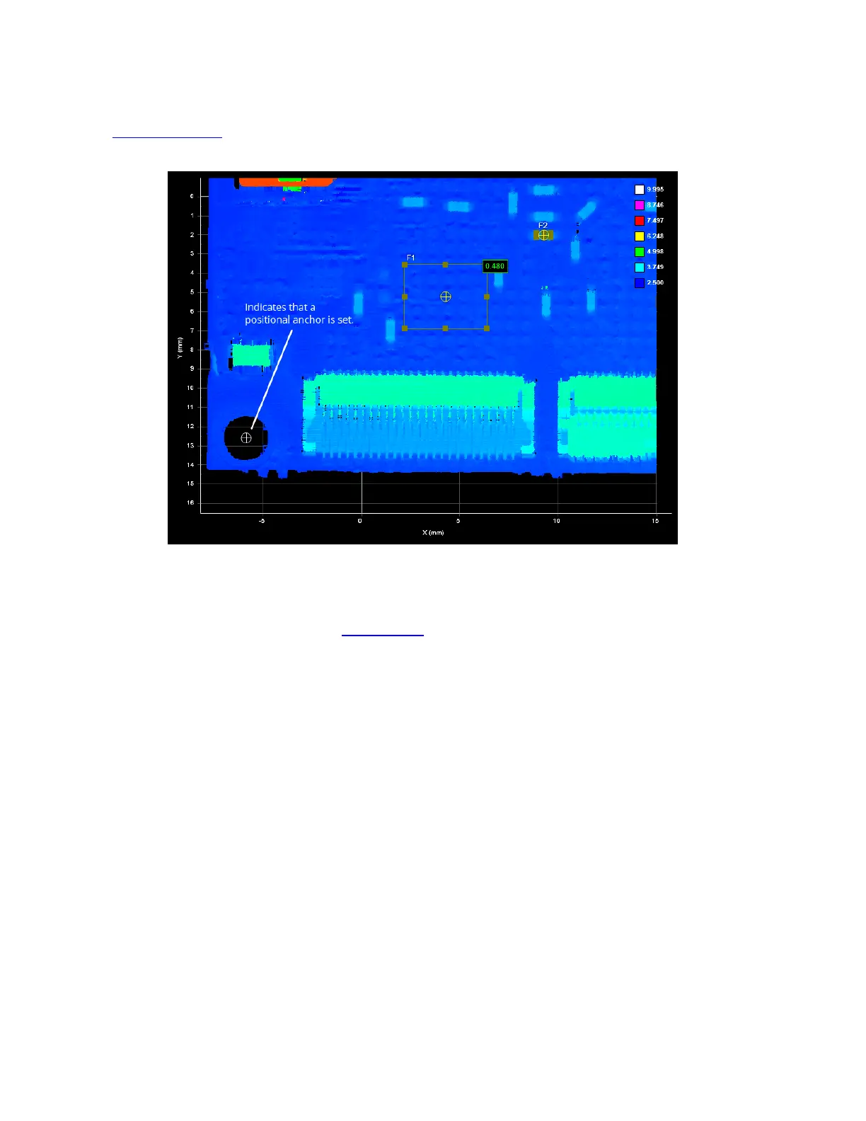
In the following image, after the Surface Dimension tool is anchored to the X and Y measurements from
a Surface Hole tool (placed over the hole to the lower left), Gocator compensates for the shift—mostly
along the Y axis in this case—and returns a correct measurement, despite the shift.
You can combine the positional anchors (X, Y, or Z measurements) with an angle anchor (a Z Angle
measurement) for optimum measurement placement. For example, in the following scan, the part has
not only shifted on the XY plane but also rotated around the Z axis. Anchoring the Surface Dimension
tool to the Z Angle measurement of a Surface Edge tool (placed on the lower edge in this case)
compensates for the rotation, and the anchored tool returns a correct measurement.
 Loading...