INTAKE-AIR SYSTEM
F–11
F
4. Complete the “AFTER REPAIR PROCEDURE”. (See F–17 AFTER REPAIR PROCEDURE.)
.
8
1
7
2
3
4
9
13
14
10
19
18
15
16
12
11
17
R
N·m {kgf·cm, in·lbf}
8.0—11.5
{82—117, 71—101}
8.0—11.5
{82—117, 71—101}
8.0—11.5
{82—117, 71—101}
20—30
{204—305,
177—265}
5—7 {51—71, 45—61}
20—30
{204—305, 177—265 }
5
6
12
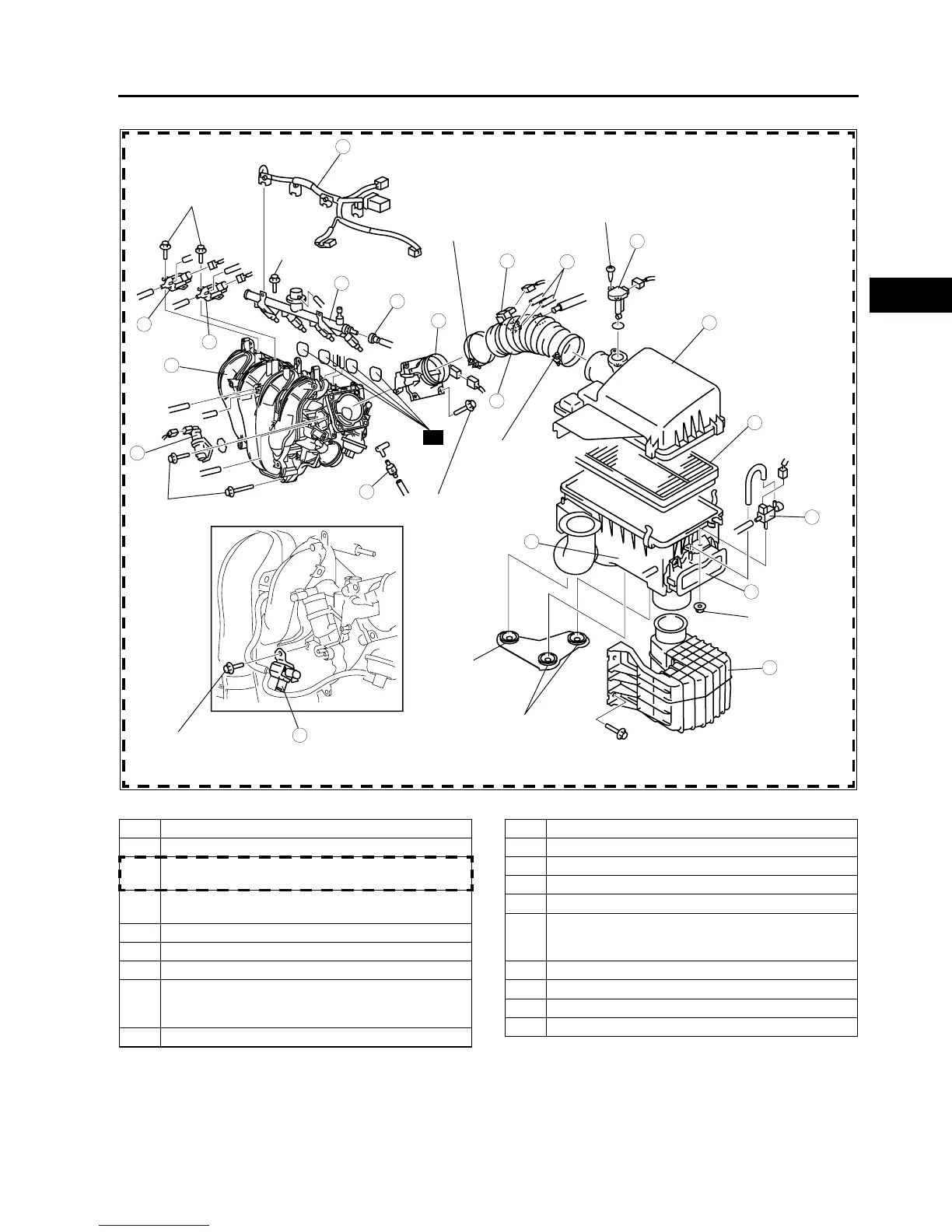
L8, LF ENGINE MODELS
0.55—0.85
{5.6—8.6, 4.9—7.5}
2.5—3.4
{26—34, 23—30}
2.5—3.4
{26—34, 23—30}
0.8—1.0
{8.2—10.0, 7.1—8.8}
RUBBER MOUNTS
(FRAME SIDE)
RUBBER MOUNT
(ENGINE SIDE)
A6E3910L001
1 Air cleaner cover
2 Air cleaner element
3 Air cleaner case
(See F–12 Air Cleaner Case Installation Note)
4 Resonance chamber
(See F–12 Resonance Chamber Removal Note)
5 VAD control solenoid valve (L3)
6 VAD shutter valve (L3)
7 Mass air flow sensor
8 Vacuum hose (purge solenoid valve)
(See F–12 Vacuum Hose (Purge Solenoid Valve)
Installation Note)
9 Purge solenoid valve
10 Air hose
11 Throttle body
12 Variable tumble control solenoid valve
13 VIS control solenoid valve (L3)
14 Fuel injector connector
15 Plastic fuel hose
(See F–28 Plastic Fuel Hose Removal Note)
(See F–30 Plastic Fuel Hose Installation Note)
16 Fuel distributor
17 Intake manifold
18 IAC valve
19 VAD check valve (L3)