P–80
ON-BOARD DIAGNOSTIC (DYNAMIC STABILITY CONTROL)
Diagnostic procedure
End Of Sie
DTC C1125
A6E697367650W10
Diagnostic procedure
End Of Sie
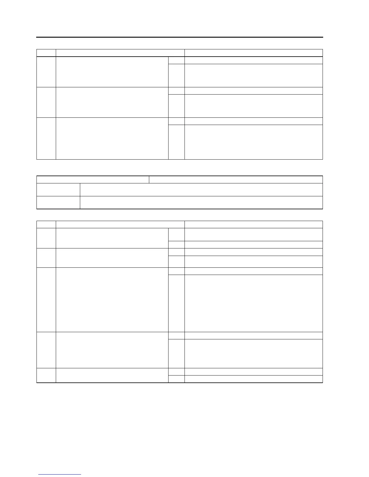
STEP INSPECTION ACTION
1 CHECK FOR PCM FOR DTCs
• Turn ignition key to OFF.
• Connect WDS or equivalent to DLC-2
• Turn ignition key to ON (engine OFF).
• Is DTC for engine control system obtained?
Yes Follow inspection procedures for engine control system.
No Go to next step.
2 MONITOR CAN SIGNAL
• Access PID RPM and TP using WDS or
equivalentI.
• Are engine speed and throttle position within
specification?
Yes Go to next step.
No Follow inspection procedures for engine control system.
3 VERIFY TROUBLESHOOTING COMPLETED
• Make sure to reconnect all disconnected
connectors.
• Clear DTC from memory.
(See P–46 Clearing DTCs Procedures)
• Start engine.
• Is same DTC present?
Yes Replace DSC HU/CM, then go to next step.
No Go to next step.
DTC C1125 Brake fluid level sensor
DETECTION
CONDITION
• Brake fluid level remains low for 5 seconds or more.
POSSIBLE
CAUSE
• Decrease in amount of brake fluid
• Malfunction of brake fluid level sensor
STEP INSPECTION ACTION
1 CHECK FOR CAN FOR DTCs
• Is any of DTC U1900 and/or U2516 has also
been stored?
Yes Follow inspection procedures for CAN system.
(See T–144 DTC U0073, U1900, U2516)
No Go to next step.
2 INSPECT BRAKE FLUID LEVEL
• Inspect brake fluid level.
• Is it okay?
Yes Go to next step.
No Add brake fluid to specified level, then go to Step 3.
3 INSPECT BRAKE FLUID LEVEL SENSOR
• Turn ignition key to OFF.
• Disconnect brake fluid level sensor
connector.
• Measure resistance between brake fluid
level sensor terminals.
— Brake fluid level above MIN: resistance
about 500 ohms
— Brake fluid level below MIN: resistance
within 0—1 ohm
• Is it okay?
Yes Go to next step.
No Repair brake fluid level sensor, then go to Next step.
4 VERIFY TROUBLESHOOTING COMPLETED
• Make sure to reconnected all disconnected
connectors.
• Clear DTC from memory.
(See P–46 Clearing DTCs Procedures)
• Is same DTC present?
Yes Replace DSC HU/CM, then go to next step.
No Go to next step.
5 VERIFY AFTER REPAIR PROCEDURE
• Is there any other DTC present?
Yes Go to applicable DTC inspection.
No Troubleshooting completed.



 To Next Page