T–20
POWER SYSTEM
FUSE BLOCK REMOVAL/INSTALLATION
A6E811066730W01
1. Disconnect the negative battery cable.
2. Remove the left-side front side trim. (See S–88 FRONT SIDE TRIM REMOVAL/INSTALLATION)
3. Remove in the order indicated in the table.
4. Install in the reverse order of removal.
End Of Sie
IGNITION SWITCH REMOVAL/INSTALLATION
A6E811066151W01
1. Disconnect the negative battery cable.
2. Remove the column cover. (See S–84 COLUMN COVER REMOVAL/INSTALLATION)
3. Remove in the order indicated in the table.
4. Install in the reverse order of removal.
End Of Sie
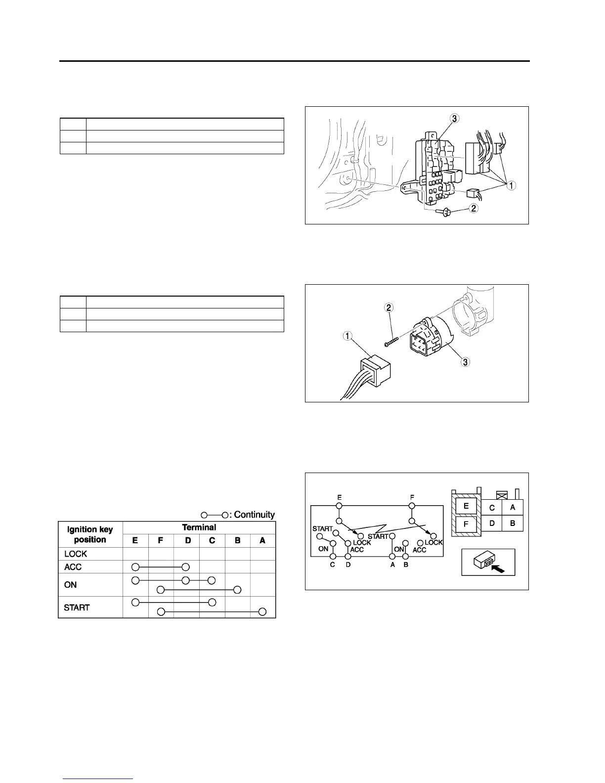
IGNITION SWITCH INSPECTION
A6E811066151W02
1. Disconnect the negative battery cable.
2. Remove the column cover. (See S–84 COLUMN COVER REMOVAL/INSTALLATION)
3. Disconnect the ignition switch connectors.
4. Inspect for continuity between the ignition switch
terminals using an ohmmeter.
• If not as specified, replace the ignition switch.
End Of Sie
1 Connector
2Bolt
3 Fuse block
A6E8110W107
1 Connector
2Screw
3 Ignition switch
A6E8110W101
A6E8110W116
A6E8110W114