OUTSIDE MIRROR
S–60–1
S
Revised 11/2004 (Ref. No. L214/04)
S–60
BODY
POWER OUTSIDE MIRROR INSPECTION
A6E773269110W03
1. Disconnect the power outside mirror connector.
2. Apply battery positive voltage to the power
outside mirror terminals and inspect the operation
of the power outside mirror.
• If not as specified, replace the power outside
mirror.
3. Inspect for continuity between the power outside
mirror heater terminals.
• If not as specified, replace the power outside
mirror.
End Of Sie
POWER OUTSIDE MIRROR SWITCH REMOVAL/INSTALLATION
A6E773266600W01
1. Disconnect the negative battery cable.
2. Remove the front door trim.
3. Remove the screws and the power outside mirror
switch.
4. Install in the reverse order of removal.
End Of Sie
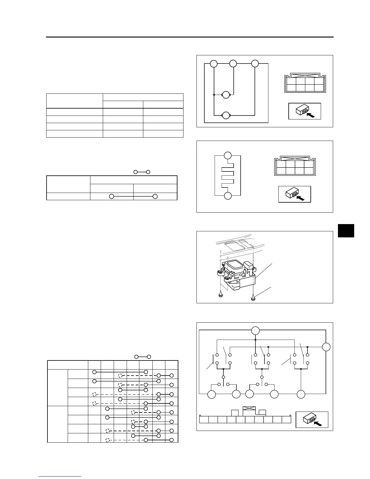
POWER OUTSIDE MIRROR SWITCH INSPECTION
A6E773266600W02
1. Inspect for continuity between the power outside
mirror switch terminals using an ohmmeter.
• If not as specified, replace the power outside
mirror switch.
OUTSIDE MIRROR
Mirror operation
Terminal
B+ GND
Up B D
Down D B
Left F D
Right D F
D
F
B
M
M
*
CE
*
B
DF
*
A6E7732W007
*
CE
*
B
DF
*
C
E
A6E7732W009
: Continuity
Mirror operation
Heater
Terminal
E
C
A6E7732W010
SCREW
POWER OUTSIDE
MIRROR SWITCH
A6E7732W008
LEFT/
UP
RH
LH
RH
LH
RIGHT/
DOWN
UP
DOWN
RIGHT
LEFT
RH
LH
B
E
C
D
F
G
H
**
HGFEDCB
*
A6E7732W001
: Continuity
OPERATION
UP
LH
RH
DOWN
LEFT
RIGHT
UP
DOWN
LEFT
RIGHT
DCEBHGF
A6E7734W003