R–4
GENERAL PROCEDURES , WHEEL ALIGNMENT
PRECAUTION (SUSPENSION)
A6E741001013W01
Wheels and Tires Removal/Installation
1. When a wheel is installed, tighten it to
88—118 N·m {9.0—12.0 kgf·m, 65.0—87.0 ft·lbf}.
Suspension Links Removal/Installation
1. Tighten any part of the suspension that uses rubber bushings only after the vehicle has been lowered and
unloaded.
Note
• Unloaded: Fuel tank is full. Engine coolant and engine oil are at specified levels. Spare tire, jack and tools
are in designated position.
Brake Lines Disconnection/Connection
Caution
• Brake fluid will damage painted surfaces. If brake fluid does get on a painted surface, wipe it off
immediately.
1. Tighten the brake pipe flare nut using the SST (49 0259 770B). Be sure to modify the brake pipe flare nut
tightening torque to allow for use of a torque wrench-SST combination.
(See GI–16 TORQUE FORMULAS.)
2. If any brake line has been disconnected anytime during the procedure, add brake fluid, bleed the brakes, and
inspect for leakage after the procedure has been completed.
Power Steering Components Removal/Installation
1. If any power steering fluid line has been disconnected anytime during the procedure, add ATF M-III or
equivalent (e.g. Dexron
®
II), bleed the fluid line, and inspect for leakage after the procedure has been
completed.
End Of Sie
WHEEL ALIGNMENT PRE-INSPECTION
A6E741201013W01
1. Inspect the tire inflation, and adjust to the recommended pressure as necessary.
2. Inspect the front wheel bearing play and correct it if necessary. (See M–4 Wheel Bearing Play Inspection.)
3. Inspect the wheel and tire runouts. (See TD–8 SUSPENSION.)
4. Inspect the ball joints and steering linkage for excessive looseness.
5. Shake the vehicle to inspect the operation of the shock absorbers.
Note
• The vehicle must be on level ground and unloaded.
• Unloaded: Fuel tank is full. Engine coolant and engine oil are at specified level. Spare tire, jack and tools
are in designated position.
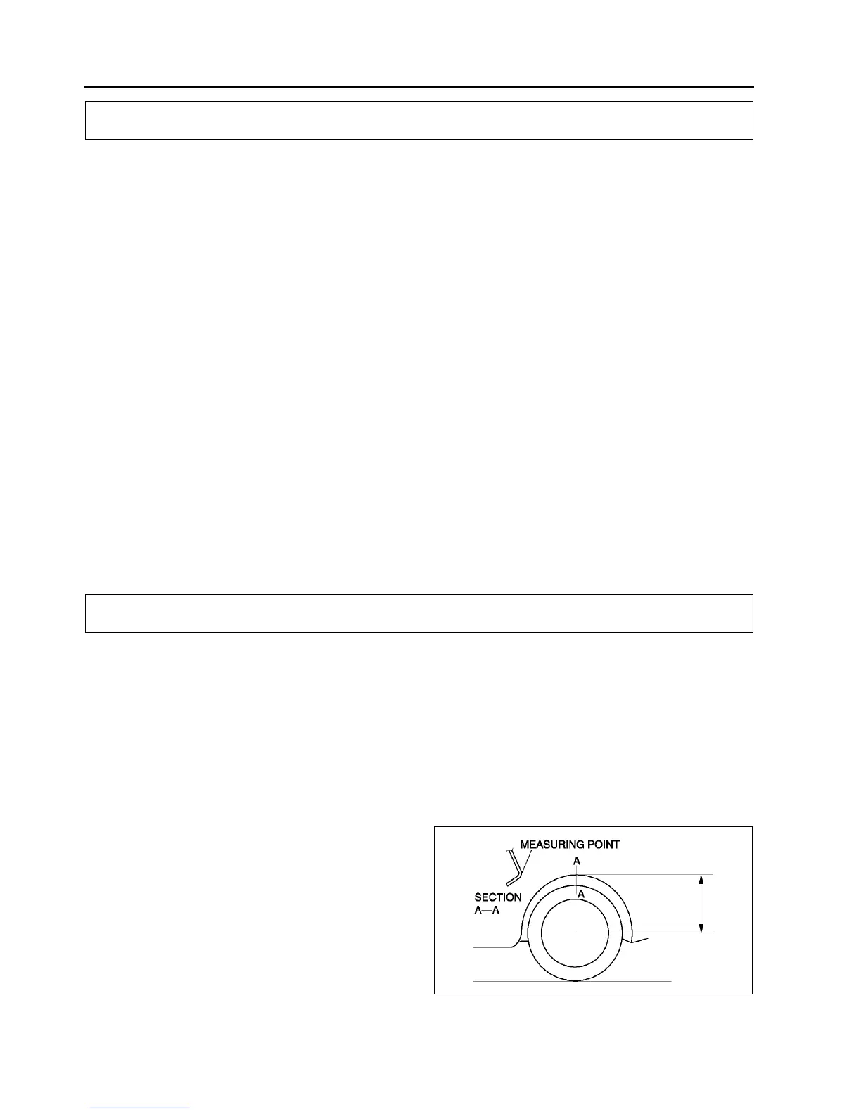
6. Measure the height from the center of the wheel
to the fender brim. The difference between the left
and right measurement must not exceed 10 mm
{0.39 in}.
End Of Sie
GENERAL PROCEDURES
WHEEL ALIGNMENT
A6E7412W001