P–44
DYNAMIC STABILITY CONTROL
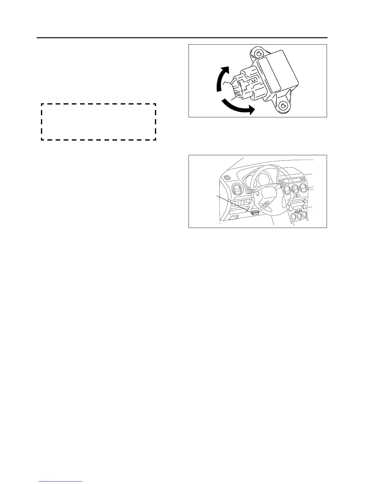
2)
Measure voltage at output terminal D and
ground terminal E when the yaw rate
sensor is rotated left and right.
Caution
• Be careful when turning the yaw rate
sensor rotation position while it is in a
reversed state because the rotation
direction and voltage will be reversed.
Voltage
Right rotation:
fluctuation between 2.5—4.62 V
Left rotation:
fluctuation between 2.5—0.33 V
End Of Sie
COMBINE SENSOR INITIALIZATION PROCEDURE
A6E692067650W07
1. Set the SST (WDS or equivalent) to the DLC-2
2. Access the active command mode and select the
YAWRATE, then follow the indication on the
monitor.
3. Select the LATACCEL and follow the indication on
the monitor.
End Of Sie
STEERING ANGLE SENSOR REMOVAL/INSTALLATION
A6E692067650W08
1. (See T–38 COMBINATION SWITCH DISASSEMBLY/ASSEMBLY.)
End Of Sie
STEERING ANGLE SENSOR INSPECTION
A6E692067650W09
1. (See T–39 STEERING ANGLE SENSOR INSPECTION.)
End Of Sie
DSC OFF SWITCH REMOVAL/INSTALLATION
A6E692067650W10
1. (See P–31 TCS (DSC) OFF SWITCH REMOVAL/INSTALLATION.)
End Of Sie
DSC OFF SWITCH INSPECTION
A6E692067650W11
1. (See P–32 TCS (DSC) OFF SWITCH INSPECTION.)
End Of Sie
A6E6920W005
DLC-2
A6E3970W002