FRONT SUSPENSION
R–23
R
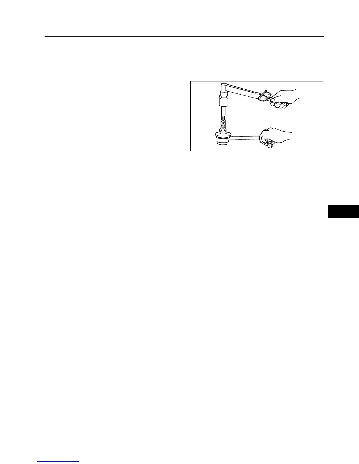
STABILIZER CONTROL LINK INSPECTION
A6E741434150W01
1. Remove the stabilizer control link from the vehicle.
2. Inspect for bending and damage.
3. Measure the ball joint starting torque.
(1) Rock the ball joint stud side to side 10 times.
(2) Rotate the ball joint stud 10 times.
(3) Measure the starting torque using a suitable
allen socket and a torque wrench.
Starting torque
0.23—0.47 N·m
{2.4—4.7 kgf·cm, 2.1—4.1 in·lbf}
End Of Sie
FRONT CROSSMEMBER REMOVAL/INSTALLATION
A6E741434800W01
1. Remove the under cover.
2. Remove the splash shield.
3. Remove the front auto leveling sensor.
(See T–32 FRONT AUTO LEVELING SENSOR REMOVAL/INSTALLATION.)
4. Remove the transverse member.
(See R–27 TRANSVERSE MEMBER REMOVAL/INSTALLATION.)
5. Remove the steering gear and linkage, and pipe assembly installation bolts from the front crossmember, then
suspend the steering gear and linkage with a cable.
Tightening torque
• Steering gear and linkage: 74.4—104.8 N·m {7.857—10.68 kgf·m, 54.88—77.29 ft·lbf}
• Pipe assembly: 7.8—10.8 N·m {79.6—110.0 kgf·cm, 69.1—95.5 in·lbf}
6. Remove in the order indicated in the table.
7. Install in the reverse order of removal.
8. Adjust the headlight zeroset.
(See T–31 HEADLIGHT ZEROSET.)
9. Inspect the front wheel alignment.
(See R–5 FRONT WHEEL ALIGNMENT.)
A6E7414W021