CONTROL SYSTEM
U–47
U
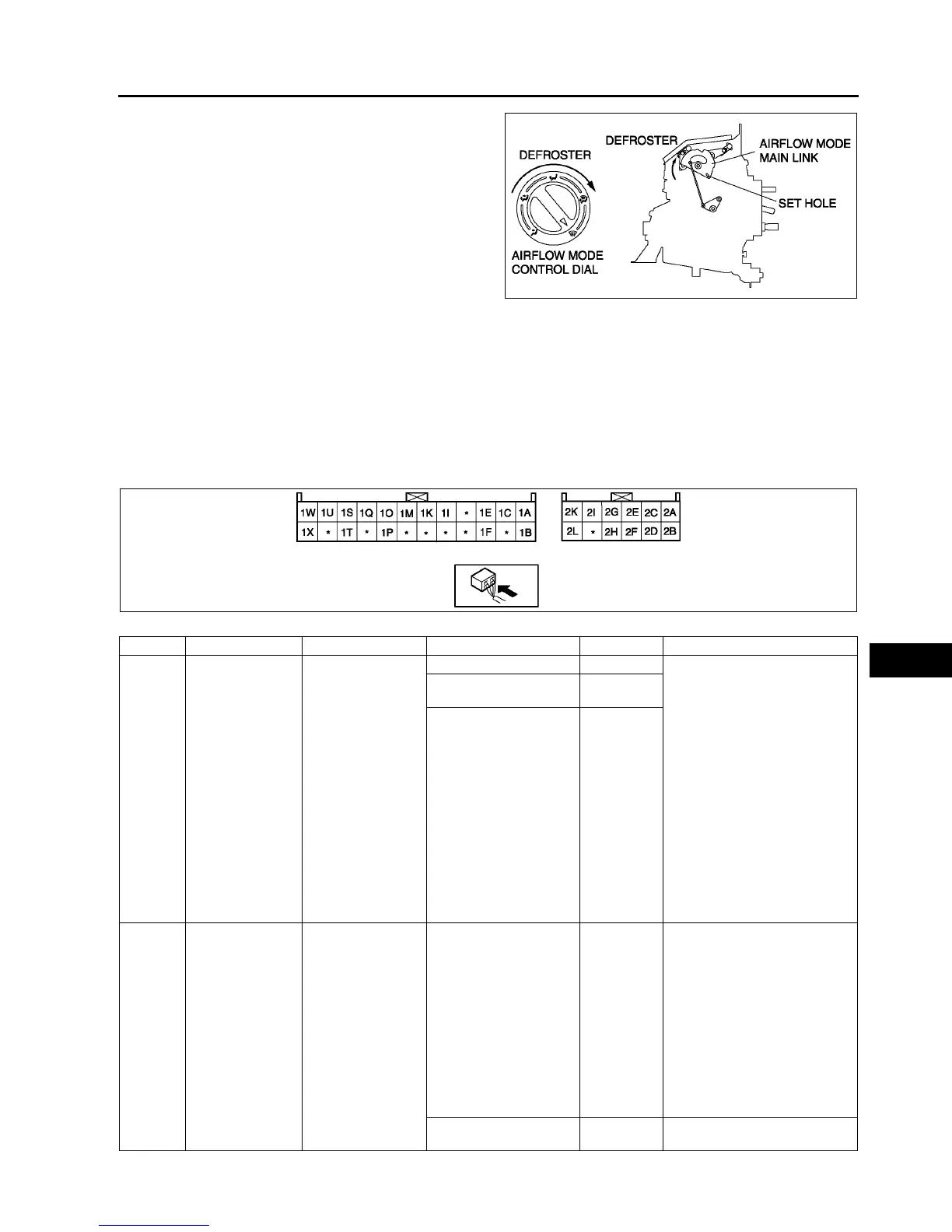
2. Set the airflow mode main link to defroster in the
direction shown by the arrow and insert a
screwdriver at the set hole.
3. Connect the airflow mode wire to airflow mode
main link.
4. Clamp the airflow mode wire to wire clamp.
5. Verify that the airflow mode control dial moves its
full stroke.
End Of Sie
CLIMATE CONTROL UNIT INSPECTION
A6E854061190W02
Full-auto Air Conditioner
1. Connect the all center panel connectors.
2. Turn the ignition switch to ON position.
3. Measure the voltage at each climate control unit terminal and refer to the terminal voltage list.
• If not as specified, inspect the parts listed under “Action” and the related wiring harness.
— If there is any malfunction, replace the climate control unit.
Terminal Voltage List (Reference)
A6E8540W035
Terminal Signal Connected to Test condition Voltage (V) Action
1A Blower motor
feedback signal
• Blower motor
• Power MOS
FET
Fan switch is OFF 12 1. Inspect for continuity or
short circuit (Climate control
unit—blower motor: 1A—B)
(Climate control unit—power
MOS FET: 1A—B, 1C—E)
(Blower motor—blower
relay: A—C) (Blower relay—
fuse: D—BLOWER 40 A
fuse)
2. Inspect for continuity (Power
MOS FET—ground: A—
GND) (Blower relay—
ground: A—GND)
3. Inspect power MOS FET
4. Inspect blower motor
5. Inspect blower relay
6. Inspect BLOWER 40 A fuse
7. Replace power MOS FET
Fan switch is at manual
LO
7.8
Fan switch is at manual
HI
0.2
1B +5 V • Air mix actuator
• Airflow mode
actuator
• Solar radiation
sensor
Ignition switch at ON
position
5.0
• Inspect for short circuit
(Climate control unit— air
mix actuator, airflow mode
actuator, solar radiation
sensor: 1B—B, B, A)
• Inspect air mix actuator
• Inspect airflow mode
actuator
• Inspect solar radiation
sensor
• Inspect terminal voltage of
climate control unit
connector (2H, 2L)
Ignition switch at LOCK
position
Below 1.0
• Replace climate control unit
A6E8540W038