ON-BOARD DIAGNOSTIC
F–159
F
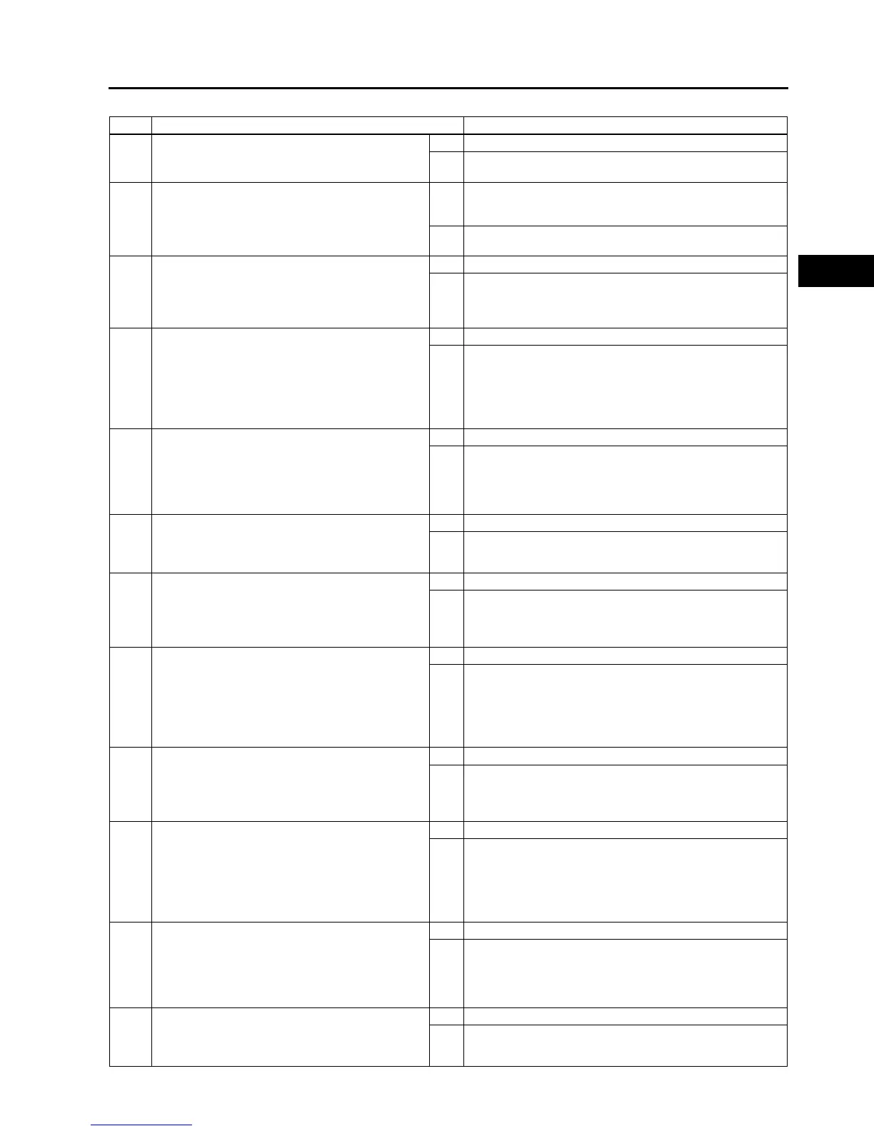
Diagnostic procedure
STEP INSPECTION ACTION
1 VERIFY FREEZE FRAME DATA HAS BEEN
RECORDED
• Has FREEZE FRAME DATA been recorded?
Yes Go to next step.
No Record FREEZE FRAME DATA on repair order, then go to
next step.
2 VERIFY RELATED REPAIR INFORMATION
AVAILABILITY
• Check for related Service information
availability.
• Is any related Service information available?
Yes Perform repair or diagnosis according to available Service
information.
• If vehicle is not repaired, go to next step.
No Go to next step.
3 CLASSIFY HIGH INPUT OR LOW INPUT
• Connect WDS or equivalent to DLC-2.
• Access CPP PID.
• Verify CPP PID during clutch pedal operation.
• Is CPP PID always OFF?.
Yes Go to Next step.
No Go to Step 10.
4 INSPECT CLUTCH SWITCH CONNECTOR FOR
POOR CONNECTION
• Turn ignition switch to OFF.
• Disconnect clutch switch connector.
• Inspect for poor connection (damaged/pulled-
out terminals, corrosion, etc.).
• Is there malfunction?
Yes Repair or replace terminal, then go to Step 14.
No Go to next step.
5 CLASSIFY CLUTCH SWITCH OR CIRCUIT
• Connect WDS or equivalent to DLC-2.
• Access CPP PID.
• Connect a jumper wire between clutch switch
terminal B and D.
• Is CPP PID on?
Yes Go to next step.
No Go to Step 7.
6 INSPECT CLUTCH SWITCH
• Perform clutch switch inspection.
(See F–59 CLUTCH SWITCH INSPECTION.)
• Is clutch switch okay?
Yes Go to Step 14.
No Replace clutch switch, then go to Step 14.
7 INSPECT CLUTCH SWITCH GROUND CIRCUIT
FOR OPEN CIRCUIT
• Inspect continuity between clutch switch
terminal D and ground.
• Is there any continuity?
Yes Go to next step.
No Repair or replace clutch switch power circuit for open, then
Go to Step 14.
8 INSPECT PCM CONNECTOR FOR POOR
CONNECTION
• Turn ignition switch to OFF.
• Disconnect PCM connector.
• Inspect for poor connection (damaged/pulled-
out terminals, corrosion, etc.).
• Is there malfunction?
Yes Repair or replace terminal, then go to Step 14.
No Go to next step.
9 INSPECT CLUTCH SWITCH SIGNAL CIRCUIT
FOR OPEN CIRCUIT
• Inspect continuity between clutch switch
terminal B and PCM terminal 1R.
• Is there any continuity?
Yes Repair or replace harness for open, then go to Step 14.
No Go to Step 14.
10 INSPECT CLUTCH SWITCH CONNECTOR FOR
POOR CONNECTION
• Turn ignition switch to OFF.
• Disconnect clutch switch connector.
• Inspect for poor connection (damaged/pulled-
out terminals, corrosion, etc.).
• Is there malfunction?
Yes Repair or replace terminal, then go to Step 14.
No Go to next step.
11 CLASSIFY CLUTCH SWITCH OR CIRCUIT
• Connect WDS or equivalent to DLC-2.
• Access CPP PID.
• Verify that CPP PID changes from ON to OFF
when clutch switch connector disconnected.
• Does CPP PID change from ON to OFF?
Yes Go to next step.
No Go to Step 13.
12 INSPECT CLUTCH SWITCH
• Perform clutch switch inspection.
(See F–59 CLUTCH SWITCH INSPECTION.)
• Is clutch switch okay?
Yes Go to Step 14.
No Replace clutch switch, then go to Step 14.