MANUAL TRANSAXLE
J–7
J
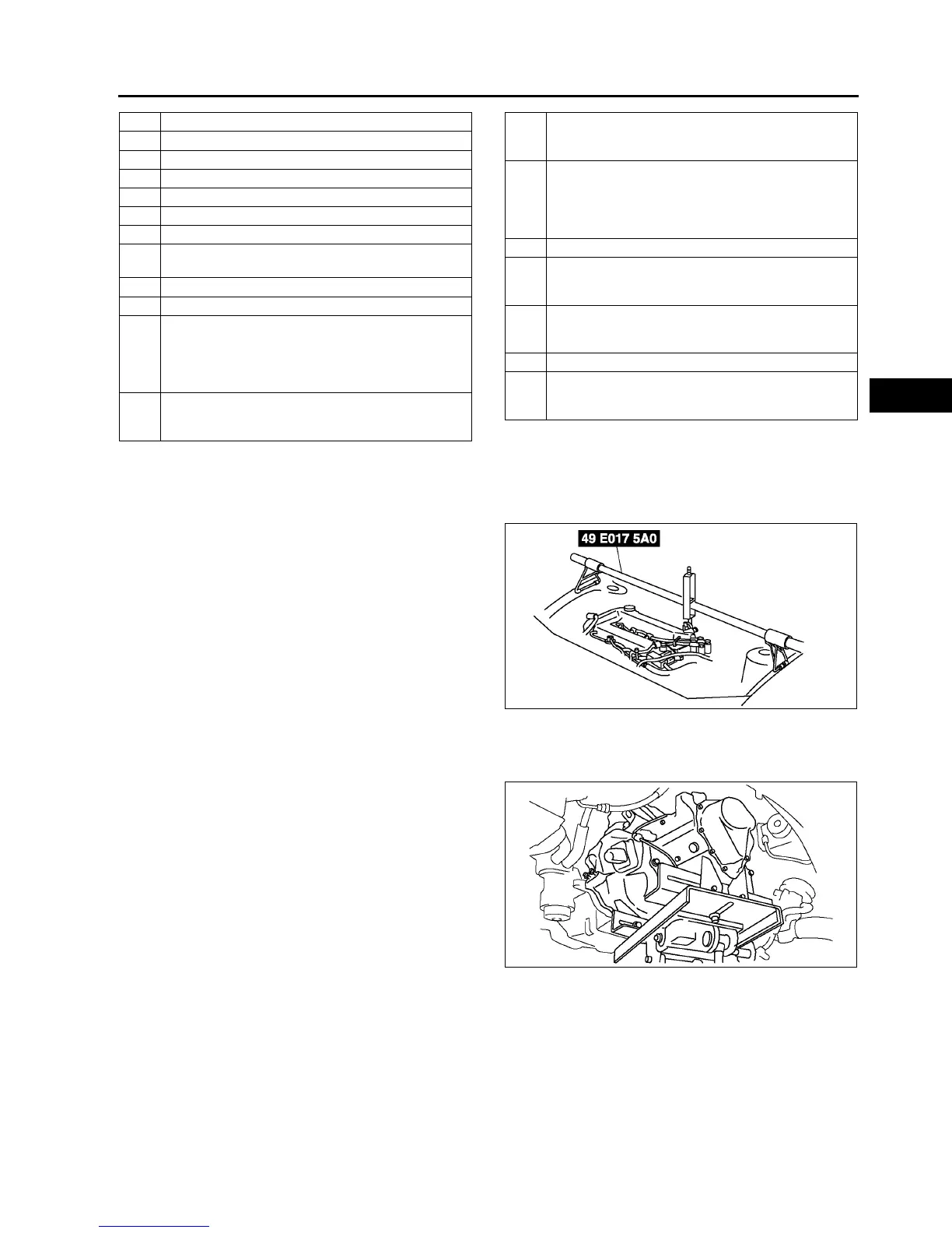
No.1 Engine Mount Bracket Removal Note
1. Support the engine using the SST before
removing the No.1 engine mount.
2. Remove the No.1 engine mount.
Manual Transaxle Removal Note
1. Loosen the SST (49 E017 5A0)and lean the engine toward the transaxle.
2. Support the transaxle on a jack.
3. Remove the transaxle mounting bolts.
4. Remove the transaxle.
6 Selector cable
7 Shift cable
8 Selector cable bracket
9 Clutch release cylinder
10 Starter
11 Endplate cover
12 Transaxle mounting bolt (upper side)
13
Tie-rod end ball joint
(See N–11 Tie-rod End Ball Joint Removal Note)
14 Stabilizer control link
15 Damper fork
16
Lower arm (front, rear) ball joint
(See R–19 Front Lower Arm (Rear) Ball Joint
Removal Note)
(See R–16 Front Lower Arm (Front) Ball Joint
Removal Note)
17
Drive shaft
(See M–17 DRIVE SHAFT REMOVAL/
INSTALLATION.)
18
Joint shaft
(See M–12 JOINT SHAFT REMOVAL/
INSTALLATION.)
19
No.1 engine mount
(See J–7 No.1 Engine Mount Bracket Removal
Note)
(See J–8 No.1 Engine Mount and No.4 Engine
Mount Bracket Installation Note)
20 Crossmember bracket
21
Crossmember component
(See R–23 FRONT CROSSMEMBER REMOVAL/
INSTALLATION)
22
No.4 engine mount
(See J–8 No.1 Engine Mount and No.4 Engine
Mount Bracket Installation Note)
23 Transaxle mounting bolt (lower side)
24
Manual transaxle
(See J–7 Manual Transaxle Removal Note)
(See J–8 Manual Transaxle Installation Note)
A6E5614W049
A6E5112W003