AUTOMATIC TRANSAXLE
K–27
K
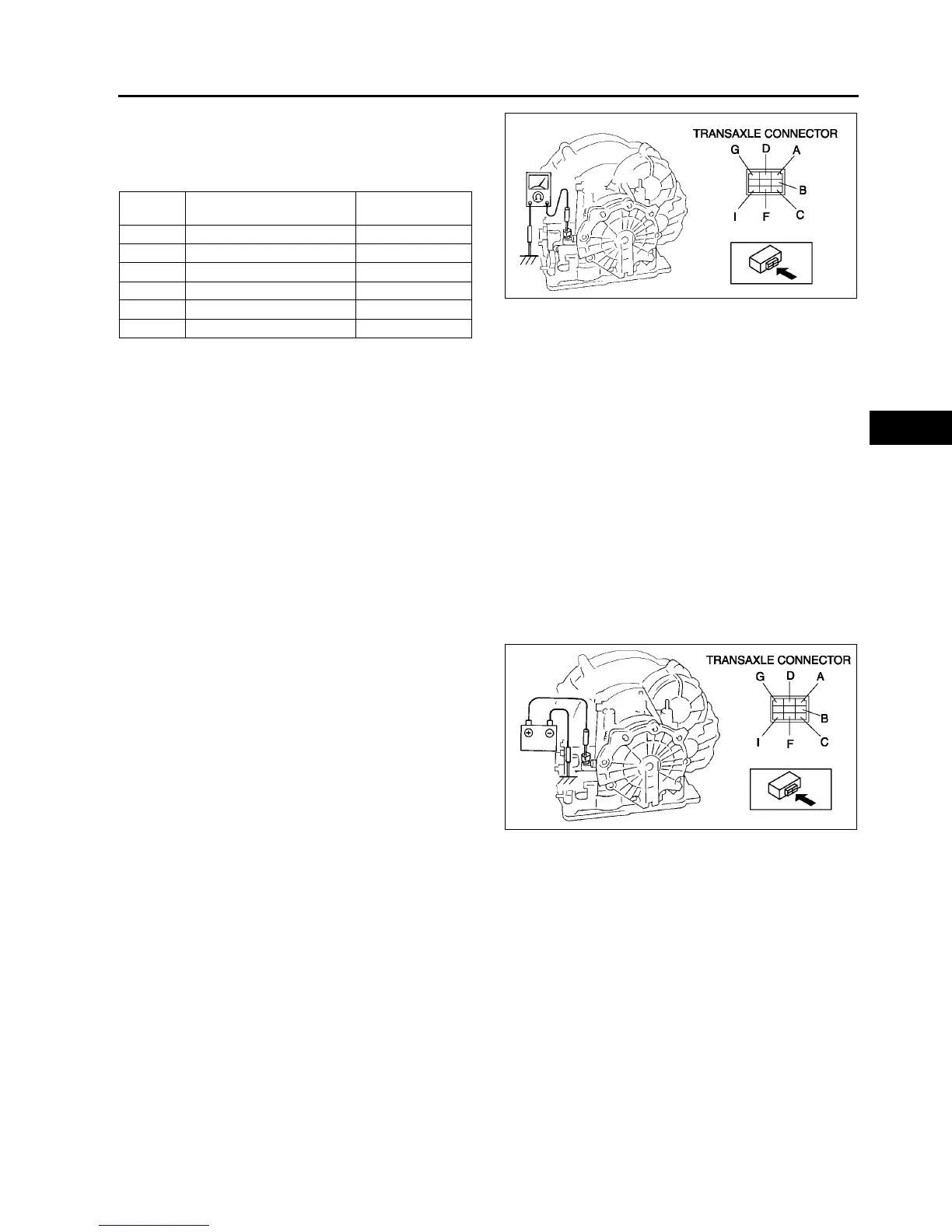
4. Measure the resistance between the following
terminals.
• If not as specified, inspect the ground, then
perform the operating inspection.
ATF temperature: –40—150 °C {–40—302 °F}
5. Connect the transaxle connector.
6. Install the air cleaner component. (See F–10 INTAKE-AIR SYSTEM REMOVAL/INSTALLATION.)
7. Connect the negative battery cable.
Operating Inspection
1. Disconnect the transaxle connector.
Caution
• Do not apply battery position voltage to terminals A, B, C, D, F and G for more than three seconds.
Note
• Because the operation sound of the valves is small, perform inspection in a quiet place.
2. Apply battery positive voltage to terminals A,B,C, F or G and battery negative voltage to GND, and verify that
operating sound is heard from solenoid.
• If the "click" is not heard, inspect the transaxle harness.
— If the transaxle harness is okay, perform the resistance inspection (off-vehicle inspection).
— If there is a problem, repair or replace the transaxle harness.
3. Apply battery positive voltage to terminal D and
battery negative voltage to terminal I, and verify
that operating sound is heard from solenoid.
• If the "click" is not heard, inspect the transaxle
harness.
— If transaxle harness is okay, perform the
resistance inspection (off-vehicle
inspection)
— If there is a problem, repair or replace the
transaxle harness.
Resistance Inspection (Off-Vehicle Inspection)
1. Remove the control valve body. (See K–28 SOLENOID VALVE REMOVAL/INSTALLATION.)
2. Measure the resistance of each solenoid valve individually.
• If not as specified, replace the solenoid valve.
3. Install the control valve body. (See K–28 SOLENOID VALVE REMOVAL/INSTALLATION.)
Terminal Solenoid valve
Resistance
(ohm)
A—GND Shift solenoid A 1.0—4.2
C—GND Shift solenoid B 1.0—4.2
G—GND Shift solenoid C 1.0—4.2
B—GND Shift solenoid D 10.9—26.2
F—GND Shift solenoid E 10.9—26.2
D—I Pressure control 2.4—7.3
A6E5614W039
A6E5614W040