AUTOMATIC TRANSAXLE SHIFT MECHANISM
K–46–1
K
K–46
AUTOMATIC TRANSAXLE
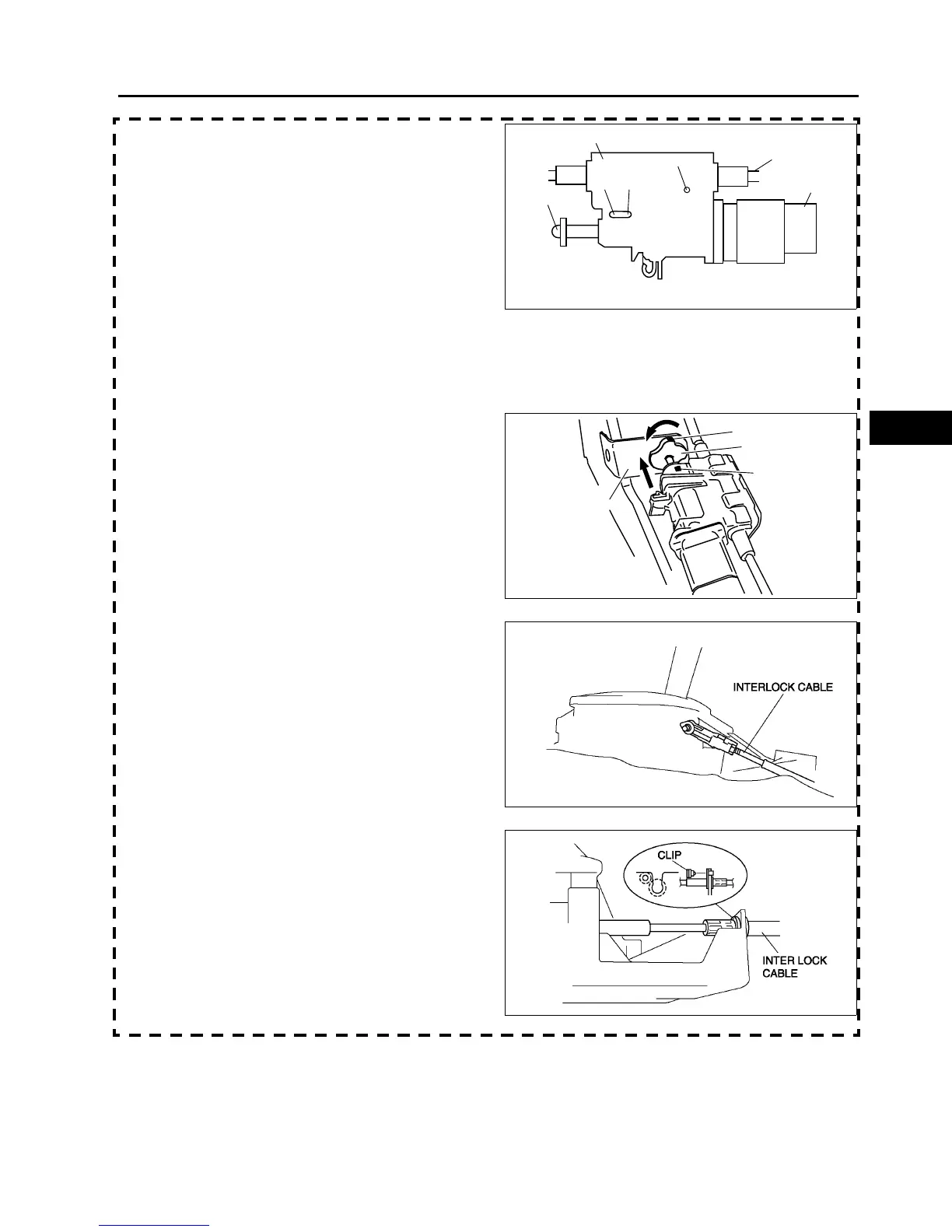
INTERLOCK CABLE ADJUSTMENT
BHE05140 9000W03A
8. Push the snap pin (or a φ1.5 round bar or
simular.) into hole A by fully pushing the slider pin
in.
9. Push the snap pin into hole B and hole C of the
lock unit until it passes through.
10. Disconnect the brake switch connector.
11. Remove the brake switch. (See P–9 BRAKE
PEDAL REMOVAL/INSTALLATION.)
12. Install the new brake switch. (See P–9 BRAKE
PEDAL REMOVAL/INSTALLATION.)
Caution
• Do not connect the brake switch
connector until the interlock cable
adjustment is completed.
13. Install the lock unit to the bracket. (See K–49 Interlock Cable Installation Note.)
14. Rotate the slider pin to release the lock, and verify that the it slides freely.
15. Verify that the slider pin contacts the brake pedal
stopper rubber and rotate the slider pin to lock.
16. Install the interlock cable end onto the interlock
link on the selector lever.
17. Fit the interlock cable in the U-groove in the
selector lever base plate and install the clip.
AUTOMATIC TRANSAXLE SHIFT MECHANISM
SLIDER PIN
INTERLOCK
CABLE
BRAKE SWITCH
A
B
C
LOCK UNIT
CHU0514W012
STOPPER
RUBBER
SLIDER PIN
MARKING
MARKING
BHE0514W011
A6E5616W010
A6E5616W011