ON-BOARD DIAGNOSTIC
K–111
K
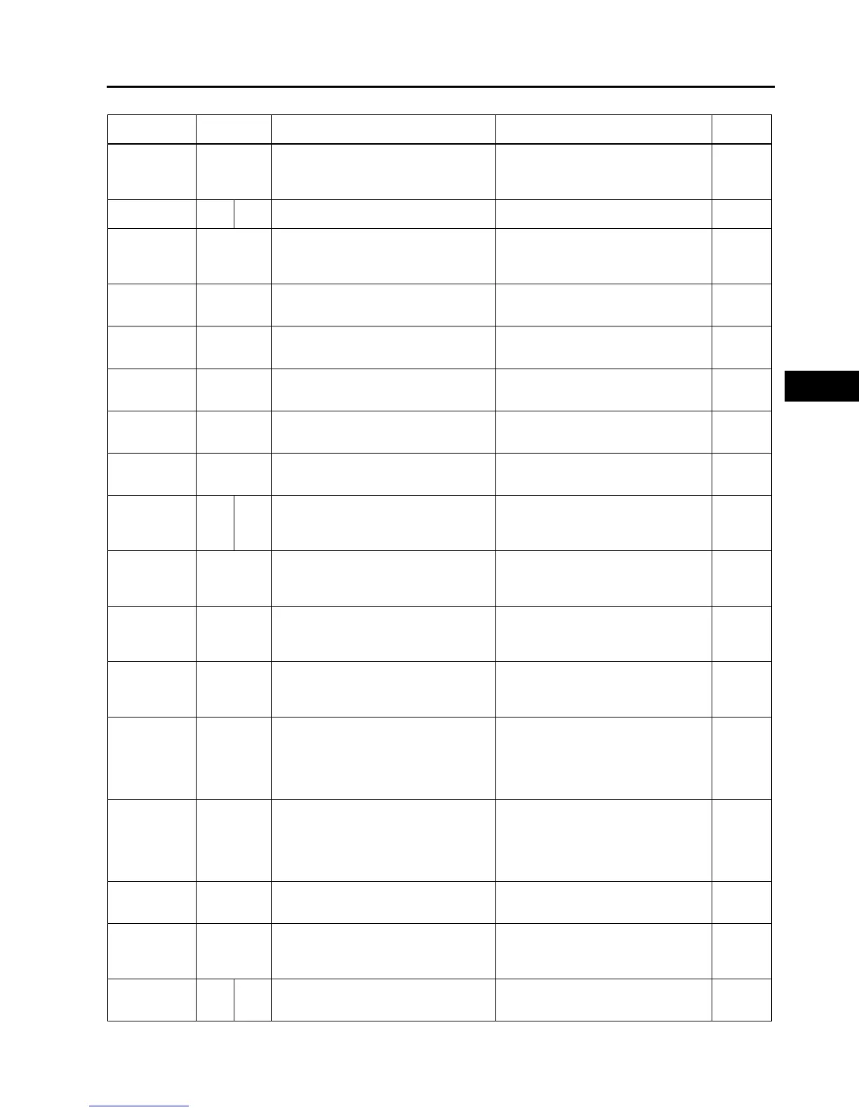
PID/DATA MONITOR AND RECORD function table
End Of Sie
Monitor item
(Definition)
Unit/
Condition
Condition/Specification Action
PCM
terminal
GEAR —
1GR: 1
2GR: 2
3GR: 3
4GR: 4
Inspect following PIDs: SSA/SS1, SSB/
SS2, SSC/SS3, SSD/SS4, SSE/SS5
3P, 3S,
3Y, 4Y,
4AB, 4AC
LINEDES kPa inHg Indicates target line pressure
Inspect following PIDs:
TFT, TFT V, VPWR, TP, TSS, VSS, TR
3V, 3Y
LPS
(Pressure
control
solenoid)
%
Change current value according to
throttle opening angle
Inspect pressure control solenoid.
(See K–26 SOLENOID VALVE
INSPECTION.)
3V, 3Y
OP SW B
(Oil pressure
switch)
ON/OFF
1, 2 or 3GR: ON
Other: OFF
Inspect oil pressure switch inspection.
(See K–21 OIL PRESSURE SWITCH
INSPECTION.)
3T
SSA/SS1
(Shift solenoid
A)
%
4GR: 99%
others: 0%
Inspect shift solenoid A.
(See K–26 SOLENOID VALVE
INSPECTION.)
4AB
SSB/SS2
(Shift solenoid
B)
%
1GR at D range: 99%
Others: 0%
Inspect shift solenoid B.
(See K–26 SOLENOID VALVE
INSPECTION.)
4AC
SSC/SS3
(Shift solenoid
C)
%
1GR/2GR: 99%
Others: 0%
Inspect shift solenoid C.
(See K–26 SOLENOID VALVE
INSPECTION.)
4Y
TCS
(HOLD switch)
ON/OFF
HOLD switch pressed: ON
HOLD switch released: OFF
Inspect HOLD switch.
(See K–13 HOLD SWITCH
INSPECTION.)
3Q
TFT
(Transaxle fluid
temperature)
°C °F Indicates transaxle fluid temperature
Inspect TFT sensor.
(See K–19 TRANSAXLE FLUID
TEMPERATURE (TFT) SENSOR
INSPECTION.)
3D
TFTV
(Transaxle fluid
signal voltage)
V
ATF 20 °C {68 °F}: 3.4—3.6 V
ATF 130 °C {266 °F}: 0.4—0.5 V
Inspect TFT sensor.
(See K–19 TRANSAXLE FLUID
TEMPERATURE (TFT) SENSOR
INSPECTION.)
3D
THOP
(Throttle
position
sensor)
%
CTP: 0%
WOT:100%
Inspect TP sensor.
(See F–51 THROTTLE POSITION (TP)
SENSOR INSPECTION.)
2A
TP
(Throttle
position sensor
signal voltage)
V
CTP: 0.4—1.5 V
WOT: 4.0—5.0 V
Inspect TP sensor.
(See F–51 THROTTLE POSITION (TP)
SENSOR INSPECTION.)
2A
TR
(Transaxle
range)
—
P position: P
R position: R
N position: N
D range: D
S range: S
L range: L
Inspect TR switch.
(See K–14 TRANSAXLE RANGE (TR)
SWITCH INSPECTION.)
1W
TR SENS
(TR switch)
V
P position: 4.34—4.79 V
R position: 3.83—4.18 V
N position: 3.05—3.50 V
D range: 2.23—2.66 V
S range: 1.46—1.84 V
L range: 0.80—1.09 V
Inspect TR switch.
(See K–14 TRANSAXLE RANGE (TR)
SWITCH INSPECTION.)
1W
TSS
(Input/turbine
speed)
rpm
Ignition switch ON: 0 rpm
Idle: 700—800 rpm (P, N position)
Indicates Input/turbine speed
Inspect input/turbine speed sensor.
(See K–23 INPUT/TURBINE SPEED
SENSOR INSPECTION.)
3G, 3J
VPWR
(Battery
positive
voltage)
V
Ignition switch ON: B+
Engine running: B+
Inspect main relay.
(See T–24 RELAY INSPECTION.)
Inspect buttery.
(See G–4 BATTERY INSPECTION.)
2Y, 2Z
VSS
(Vehicle speed)
km/h mph Indicates vehicle speed
Inspect VSS.
(See K–24 VEHICLE SPEEDOMETER
SENSOR (VSS) INSPECTION.)
3C