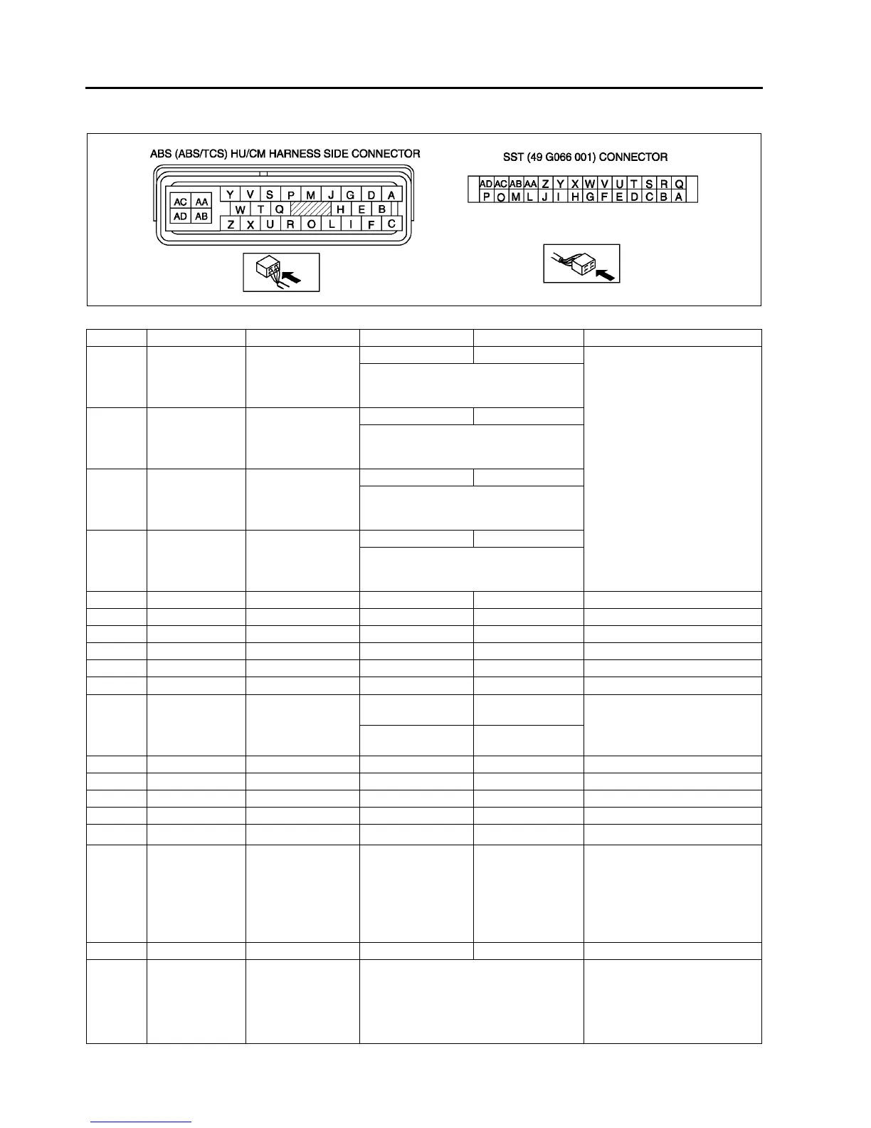
P–30
ABS/TCS
Terminal Voltage Table (Reference)
(Engine is idling, and connector is connected unless otherwise indicated.)
Terminal Signal Connected to Test condition Voltage (V) Action
A
B
RR wheel-speed
RR wheel-speed
sensor
Vehicle is stopped 0 (AC)
• Inspect related harness
• Inspect ABS wheel-speed
sensor
• Inspect by using the wave profile.
(See P–31 Inspection Using An
Oscilloscope (Reference))
C
F
LR wheel-speed
LR wheel-speed
sensor
Vehicle is stopped 0 (AC)
• Inspect by using the wave profile.
(See P–31 Inspection Using An
Oscilloscope (Reference))
G
D
RF wheel-speed
RF wheel-speed
sensor
Vehicle is stopped 0 (AC)
• Inspect by using the wave profile.
(See P–31 Inspection Using An
Oscilloscope (Reference))
I
E
LF wheel-speed
LF wheel-speed
sensor
Vehicle is stopped 0 (AC)
• Inspect by using the wave profile.
(See P–31 Inspection Using An
Oscilloscope (Reference))
H —— — — —
K —— — — —
L —— — — —
M —— — — —
N —— — — —
OCAN-H ——No need to check —
P*
1
TCS OFF switch TCS OFF switch
When switch is
pressed
Below 1.0
• Inspect related harness
• Inspect TCS OFF switch
When switch is not
pressed
B+
Q —— — — —
RCAN-L ——No need to check —
S —— — — —
T —— — — —
U*
2
— DLC — No need to check —
V
Vehicle speed
output
Cruise actuator,
Wiper and washer
switch,
Audio unit,
Car-navigation unit,
Headlight leveling
actuator
Vehicle is stopped 0
• Inspect related harness
• Inspect ABS wheel-speed
sensor
W —— — — —
XOBD
KLN terminal of
DLC-2
It cannot be determined with terminal
voltage whether the condition is good or
bad because advanced function
diagnostic output is performed with
serial communication. Inspect with
service codes.
• Inspect related harness
• Inspect ABS/TCS HU/CM
A6E6921W001