STP
513
Managed Switches
Web Interface: Configure PVSTP
You must configure PVSTP on Switch 1 and Switch 2. This example assumes that all
switches can support PVSTP.
Web Interface: Configure PVSTP on Switch 1
1. Ensure that ports 1/0/1 and 1/0/2 are in VLAN 1002 in tagged mode because BPDU
packets for PVSTP are transmitted in tagged packets.
2. Enable PVSTP.
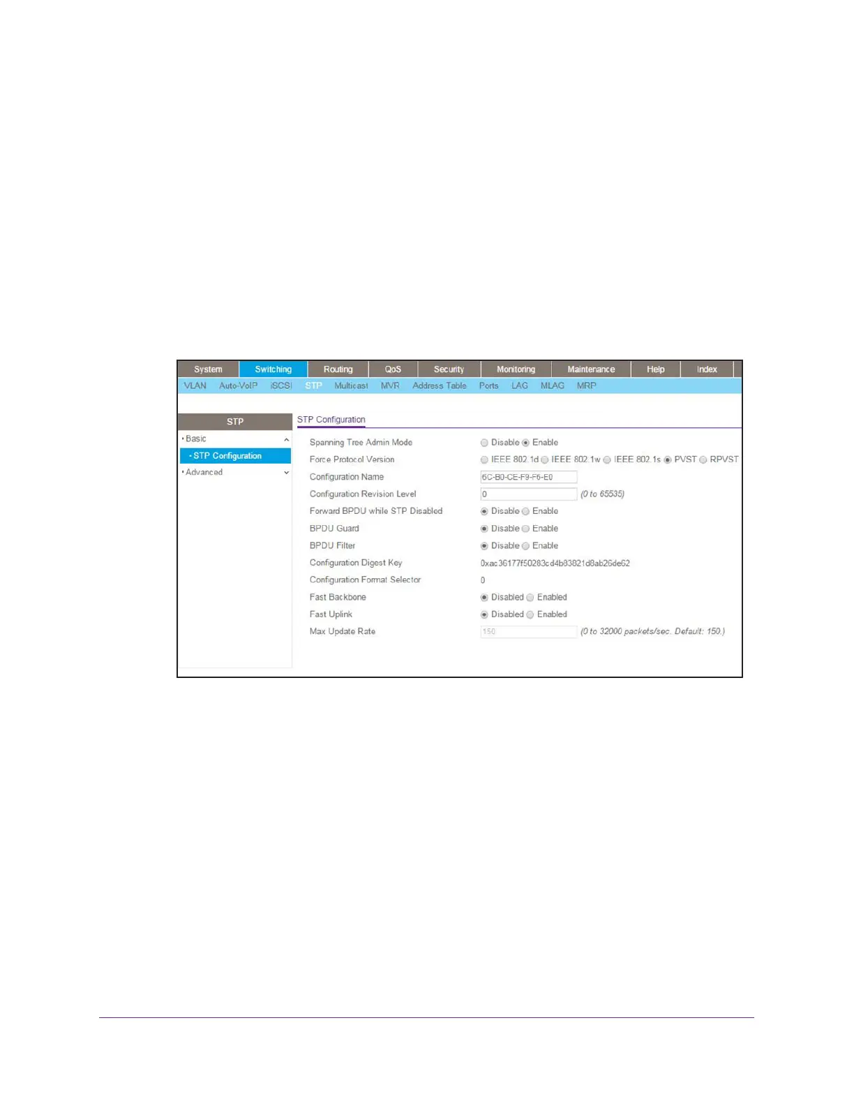
a. Select Switching > STP > Basic > STP Configuration.
A screen similar to the following displays.
b. Configure the following settings:
• For Spanning Tree Admin Mode, select the Enable radio button.
• For Force Protocol Version, select the PVST radio button.
c. Click Apply.
Note: After you enable PVST globally, PVST is applied to VLANs automatically.
3. Display the PVST status for port 1/0/1 and 1/0/2 in VLAN 1002.
a. Select Switching > STP > Advanced > PVST Interface.
A screen similar to the following displays.