EasyManua.ls Logo

Nordson Spectrum II Series User Manual

Nordson Spectrum II Series
262 pages
To Next Page IconTo Next Page
To Previous Page IconTo Previous Page
Page #104 background imageLoading...
Page #104 background image
4-32 Operation
4.10.7.2 Dot Parameters
You can control the size and accuracy of dot dispensing by setting dot parameters. You may define up to
ten different dot styles. The dot style is selected when entering a dot dispensing instruction into your
program.
Dot parameters are divided into three categories according to when each parameter is implemented during
the dispensing process. Parameters include items such as settling time, dispense gap, valve-on time, and
retract distance.
To edit dot parameters:
1. In the Programming Window, click on
Edit > Edit Dot Parameters from the menu bar.
 A window may open indicating the type of valve installed on your dispensing system
and which valve, Valve 1 or Valve 2, is currently active.
2. Click on
OK.
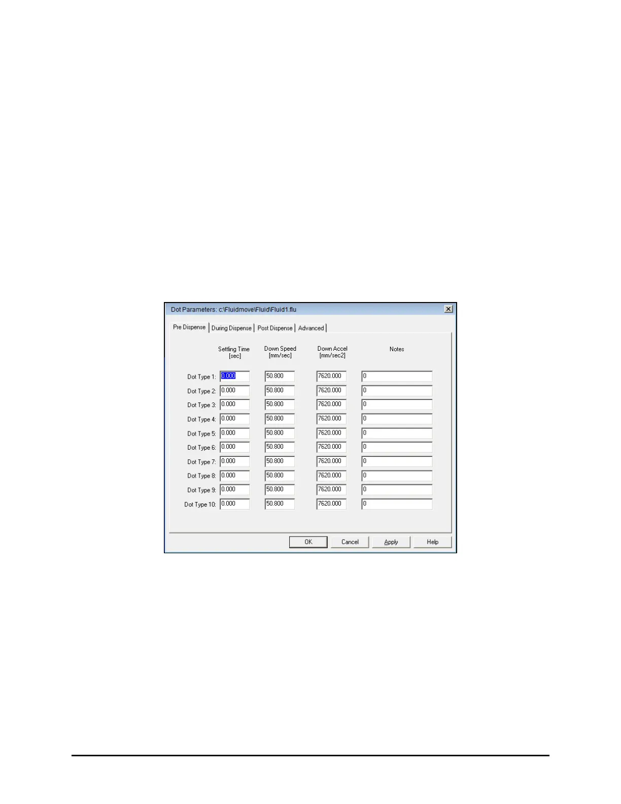
 The Dot Parameters window opens (Figure 4-27).
 Refer to the Fluidmove User Guide or Online Help for a description of the options.
Figure 4-27 Dot Parameters
3. Click on the desired tab and enter the new value in the appropriate text box.
4. Click
OK when done.
 The Dot Parameters window will close.
5. Dot parameters are saved in the fluid file. Select
File > Fluid Table > Save in the
Programming Window to save the dot parameters.
 NOTE When you edit dot parameters, it affects all dots in the program associated with that style.
If you just want to change parameters for one dot in a program, you should define a
new style.

Table of Contents

Question and Answer IconNeed help?

Do you have a question about the Nordson Spectrum II Series and is the answer not in the manual?

Nordson Spectrum II Series Specifications

General IconGeneral
TypeAutomated Dispensing System
Fluid CompatibilityWide range of adhesives, sealants, lubricants, and other fluids
ApplicationElectronics assembly, and other industrial applications
Dispensing MethodAuger
Dispense Volume RangeFrom microliters to milliliters, depending on valve and configuration
Valve Optionspneumatic
MountingBenchtop
Air SupplyRequires clean, dry compressed air

Summary

1 Introduction

1.1 Overview

Provides an overview of the S2-900 Series dispensing system and its applications.

1.3 Safety First

Highlights the importance of understanding hazards, risks, and safety precautions for operation.

1.9 S2-900 Series Features

Details standard and optional features across S2-900, S2-900P, and S2-9XXC models.

1.10 Feature Description

Provides detailed descriptions of various system features like CPJ, EMO, and Interlocks.

2 Safety

2.1 Overview

Outlines essential safety information for operating and servicing the S2-900 Series Dispensing System.

2.4 Basic Safety Precautions and Practices

Recommends precautions to reduce risks of personal injury or property damage during operation and maintenance.

2.8 Safety Warning Labels

Identifies and describes safety warning labels on the S2-900 system for hazard awareness.

2.11 Emergency Shutdown

Explains how to activate the EMO button for immediate system shutdown in emergencies.

2.14 Lockout/Tagout of Electrical and Pneumatic Energy

Details LOTO procedures for safely de-energizing equipment during maintenance.

3 Installation

3.5 Uncrating and Placing the Dispensing System

Provides step-by-step instructions for safely uncrating and positioning the dispensing system.

3.7 Leveling the Dispensing System

Guides on how to level the dispensing system using a box level and adjusting the feet.

3.11 Anchoring the Dispensing System

Guides on how to anchor the dispensing system to the floor using bolts for stability.

3.12 Connecting the Power and Air Supply

Details how to connect the system to facility power and air supply, emphasizing safety.

4 Operation

4.3 Powering on the Dispensing System

Step-by-step guide to powering on the dispensing system, including checks for power, air, and interlocks.

4.4 Starting Fluidmove for Windows

Instructions for launching and starting the Fluidmove software, including initial checks.

4.6 Adjusting the Air Pressure

Details how to set air pressure manually at regulators or via Fluidmove software.

4.7 Jog Window

Explains using Fluidmove Jog Controls to reposition the dispensing head and adjust conveyor rails.

4.9 Valve Offsets

Explains the semi-automated Valve Offsets routine to establish machine offset parameters.

4.10 Creating a New Program

Covers the steps required to create a new dispensing program, from alignment to saving.

4.11 Running Production

Details the steps for running production, from installing components to monitoring the run.

4.13 System Shutdown

Steps for shutting down the dispensing system and computer, and de-energizing the system.

5 Calibration and Adjustment

5.5 Focusing the Camera

Guides on focusing the camera by adjusting the lens and performing rough and fine focus.

5.6 Calibrating the Camera

Step-by-step process for calibrating the camera using the Setup Vision Window.

5.8 Calibrating the Scale

Instructions for calibrating the scale using the Scale Setup window and a calibration weight set.

5.9 Adjusting the Z-Head Counterbalance Force

Procedure to adjust the Z-head counterbalance force to prevent crashing and accommodate payloads.

5.14 Calibrating the Heaters

Calibrating heaters to ensure workpiece is heated to proper temperature by comparing setpoints to actual measurements.

5.16 Adjusting Manual Airflow for Impingement Heaters

Adjusting airflow to impingement heaters using flowmeter knobs based on workpiece and temperature factors.

6 Maintenance

6.4 Routine Maintenance Procedures

Details routine maintenance tasks and their recommended frequencies and instructions.

6.5 Replacing Consumables

Identifies common consumables like purge boots and scale cups that need regular replacement.

6.10 Lubricating the Cables and Linear Guides

Explains the importance of lubricating cables and linear guides for smooth dispensing head movement.

6.12 Adjusting the Linear Encoders

Procedures for adjusting linear encoders to ensure accurate positioning of the dispensing head.

6.13 Tensioning the Conveyor Belts

Instructions for tensioning conveyor belts by adjusting the belt tensioner screw and pulley.

7 Troubleshooting

7.4 Basic System Troubleshooting

Covers common troubleshooting steps for system power, accuracy, and pneumatic issues.

7.4.5 Dispense Head Controller Connections and Functions

Troubleshooting for dispense head controller initialization, Z-axis positioning, and fluid dispensing errors.

7.4.8 Conveyor

Troubleshooting for conveyor issues such as rails/belts not moving, inoperative stop pins, and transfer problems.

7.4.10 Vision System

Troubleshooting for vision system problems like no image, camera LEDs, unfocused images, and errors.

8 Parts Replacement

8.3 Parts Ordering Information

Details on how to order parts, including contact information and required details.

8.10 Replacing the Conveyor Belts

Guidelines for checking conveyor belt condition and replacing worn or broken belts.

8.11 Replacing the Camera Lens

Procedures for replacing the camera lens, including removing the camera assembly and aperture disk.

8.13 Replacing Fuses

Procedures for replacing fuses, including mounting types and a list of replaceable fuses.

9 Specifications

9.2 Facility Requirements

Details facility requirements, including system footprint, power, air supply, and environmental conditions.

9.4 System Dimensions

Provides system dimensions for the S2-900 and S2-9XXC models.

9.5 Stability Analysis

Provides data on center of gravity, weight distribution, seismic loading, and tilt angles for system stability.

Appendix A Material Safety Information

A.2 Safety Data Sheets

Lists safety data sheets for specific greases: Multemps PS NO 2, Moly-Graph, and NSK Clean Grease LG2.

A.2.1 Multemps PS NO 2

Provides the Safety Data Sheet for Multemps PS NO 2, including identification, hazards, and first aid.

A.2.2 Moly-Graph Extreme Pressure Multi-Purpose Grease

Provides the Safety Data Sheet for Moly-Graph grease, detailing hazards, first aid, and handling.

Appendix B Block Diagrams

B.2 List of Pneumatic and Electrical Diagrams

Lists available pneumatic and electrical block diagrams referenced in Table B-1.

B.3 Power Manager Connections

Illustrates and lists the connections for the Power Manager, detailing its various ports and functions.

B.4 Conveyor/Heater Module Connections

Shows and describes the connections for the Conveyor/Heater Module's front and rear views.

Related product manuals