Sample ERPv2 Ring Configuration Configuring ERP
page 11-24 OmniSwitch AOS Release 7 Network Configuration Guide June 2013
Sample ERPv2 Ring Configuration
This section provides an example network configuration in which ERPv2 is configured on network
switches to maintain a loop-free topology. In addition, a tutorial is also included that provides steps on
how to configure the example network topology using the Command Line Interface (CLI).
Example ERPv2 Overview
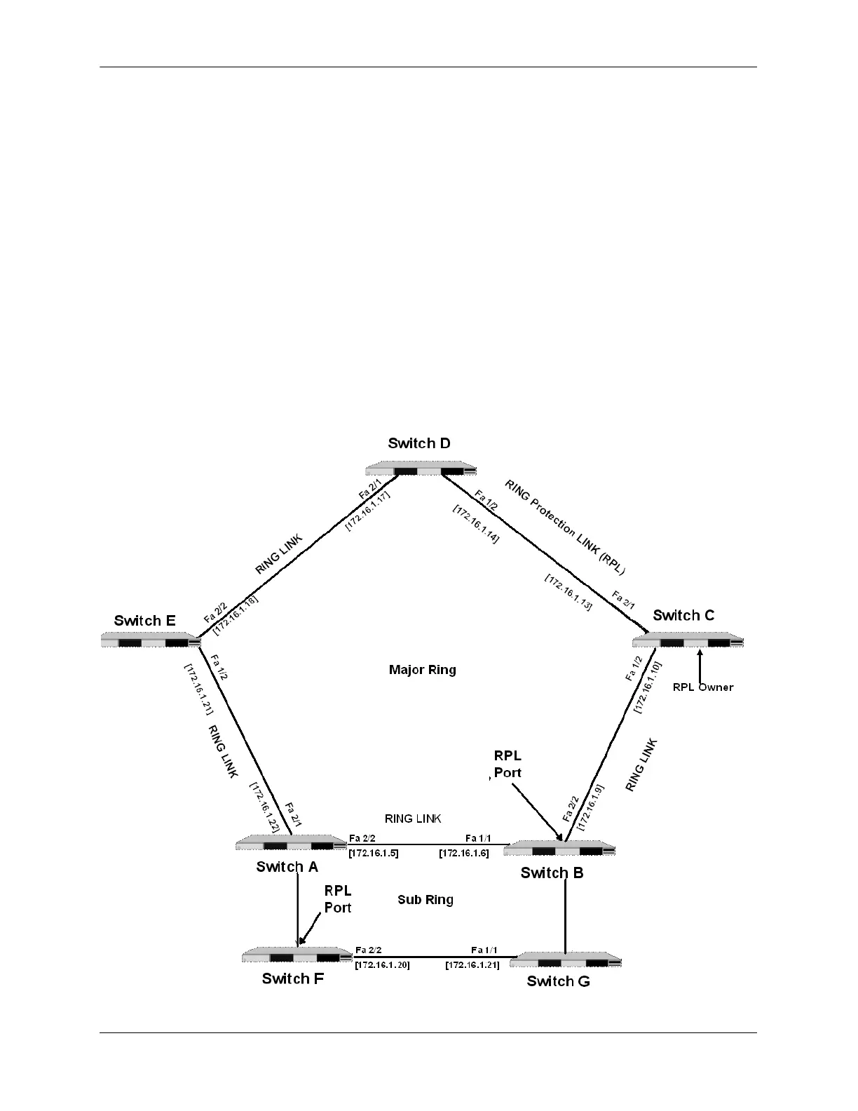
The following diagram shows a seven-switch ERPv2 ring configuration when R-APS virtual channel is
enabled.
The topology of the network is as follows:
• Switches A, B, C, D, and E for the Major Ring.
• Switch A and B form a shared link.
• Switch B is configured to be the main RPL node.
• Switches A, B, F, and G form the Sub Ring.
 Loading...