Sample Ethernet Ring Protection Configuration Configuring ERP
page 11-22 OmniSwitch AOS Release 7 Network Configuration Guide June 2013
Sample Ethernet Ring Protection Configuration
This section provides an example network configuration in which ERP is configured on network switches
to maintain a loop-free topology. In addition, a tutorial is also included that provides steps on how to
configure the example network topology using the Command Line Interface (CLI).
Example ERP Overview
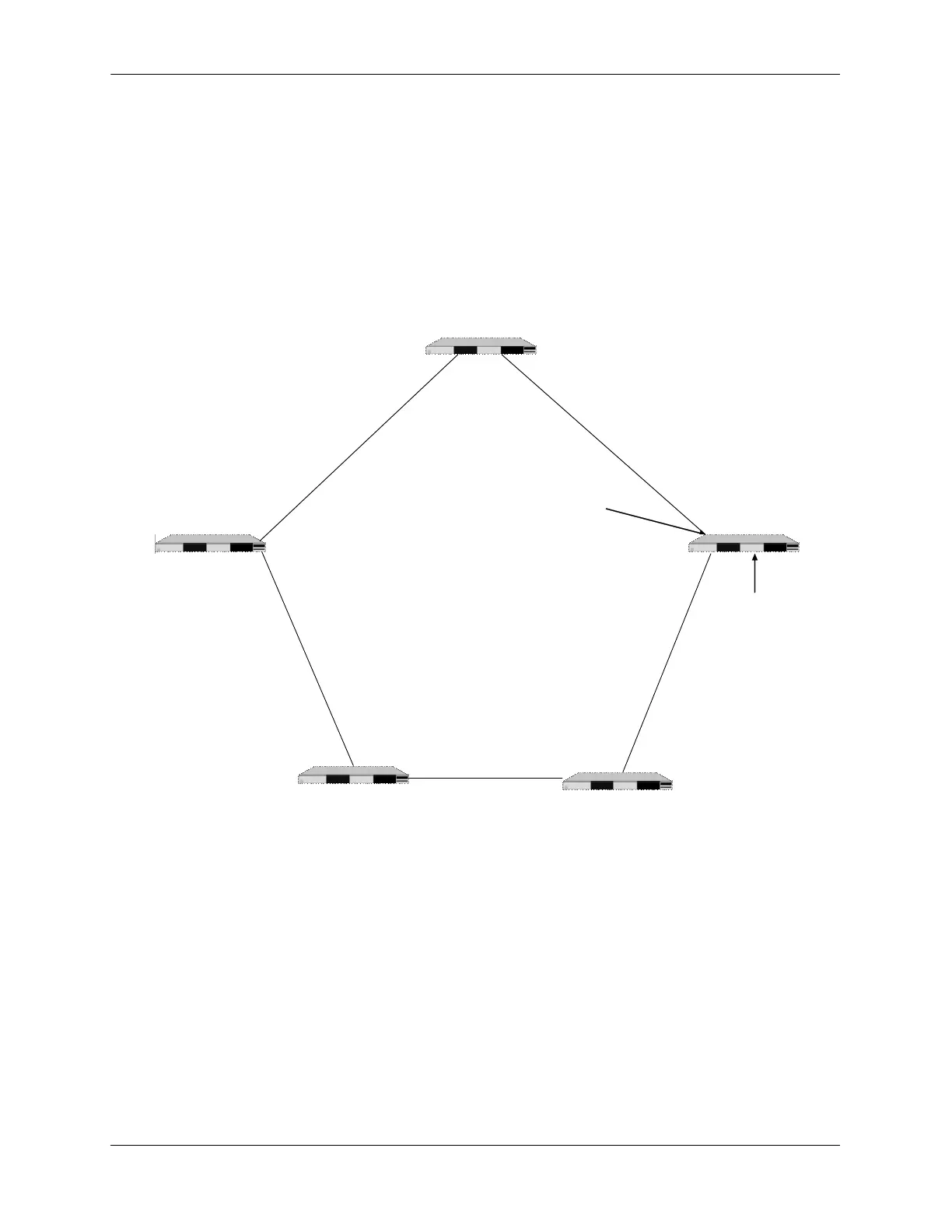
The following diagram shows a five-switch ERP ring configuration:
Configuring the sample ERP ring network shown in the above diagram involves the following tasks:
1 Configure an ERP ring with ERP ring ID 1 on all switches in the network.
2 Define an ERP Service VLAN as VLAN 10 on all switches.
3 Set the Management Entity Group (MEG) level to 2 for all switches.
4 Switch C is the RPL owner; configure the port connected to the Ring Protection Link as a RPL port.
5 Enable the configured ERP ring.
6 Assign VLANs 11-20 as a protected VLANs to ERP ring 1.
7 Use the default settings for the guard timer and WTR timer values. These values can be adjusted as
necessary.
Switch DSwitch D
Switch CSwitch C
Switch ESwitch E
Switch ASwitch A
Switch BSwitch B
F
a
2
/
2
[
1
7
2
.
1
6
.
1
.
1
8
]
F
a
2
/
1
[
1
7
2
.
1
6
.
1
.
1
7
]
F
a
1
/
2
[
1
7
2
.
1
6
.
1
.
1
4
]
F
a
2
/
1
[
1
7
2
.
1
6
.
1
.
1
3
]
F
a
1
/
2
[
1
7
2
.
1
6
.
1
.
1
0
]
F
a
2
/
2
[
1
7
2
.
1
6
.
1
.
9
]
Fa 2/2
[172.16.1.5]
Fa 1/1
[172.16.1.6]
F
a
2
/
1
[
1
7
2
.
1
6
.
1
.
2
2
]
F
a
1
/
2
[
1
7
2
.
1
6
.
1
.
2
1
]
RPL
Port
R
I
N
G
L
I
N
K
R
I
N
G
L
I
N
K
R
I
N
G
L
I
N
K
RING LINK
R
I
N
G
P
r
o
t
e
c
t
i
o
n
L
I
N
K
(
R
P
L
)
RPL Owner
 Loading...