22
Orientation to Inverter Features Section 2-1
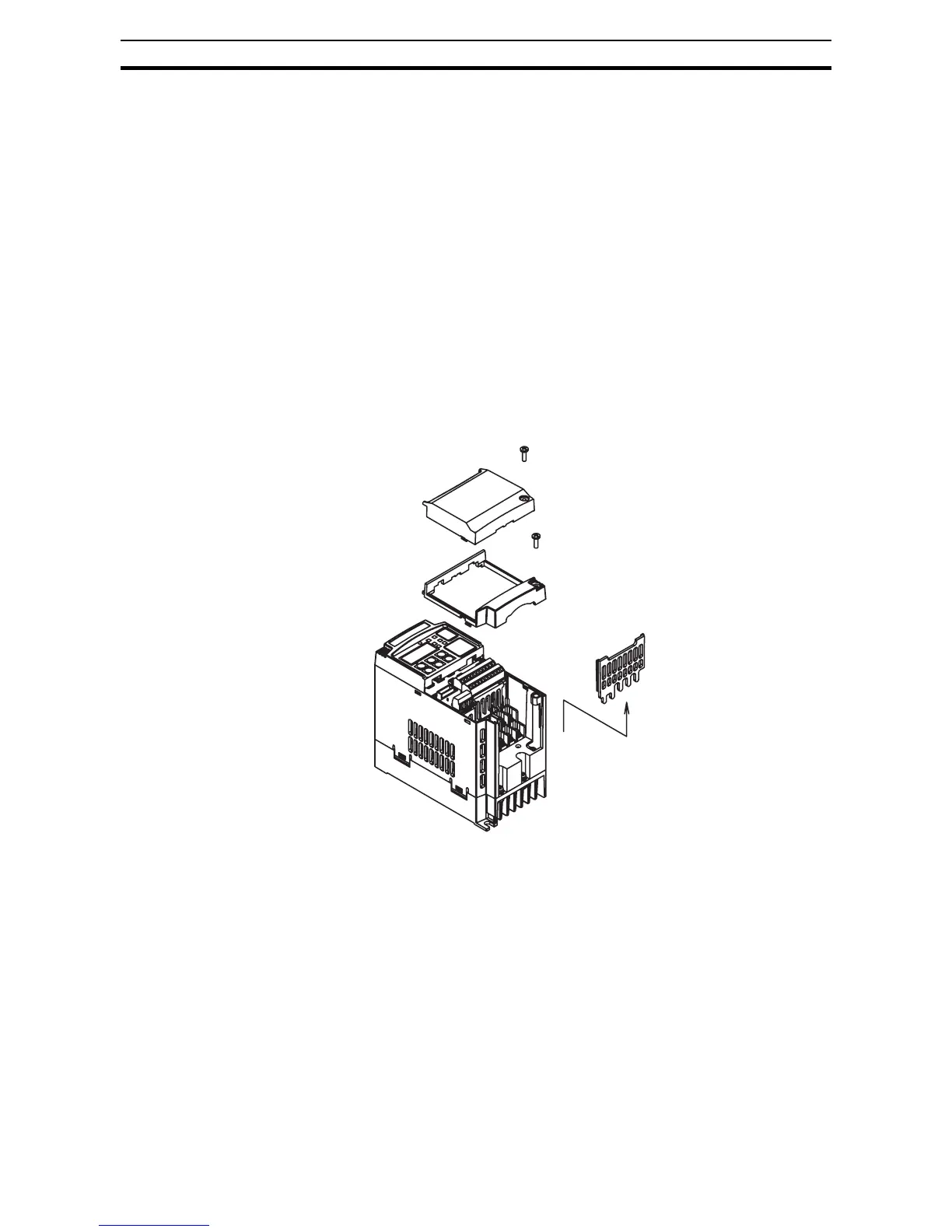
Power Wiring Access - First, ensure no power source is connected to the
inverter. If power has been connected, verify that the Power LED is OFF and
then wait ten minutes after power down to proceed. After removing the termi-
nal cover and front housing cover, the housing partitions that cover the power
and motor wiring exits will be able to slide upward as shown below.
Notice the four wire exit slots in the housing partition. This helps keep the
power and motor wiring (to the left) separated from the signal-level logic or
analog wiring (to the right).
Remove the housing partition and as shown as set them aside in a secure
place while wiring. Be sure to replace them afterward. Never operate the
inverter with the partition removed or the front housing cover removed.
The power input and motor 3-phase wiring connect to the lower row of the ter-
minals. The upper row of power terminals connect to optional braking units or
DC link choke.
The following section in this chapter will describe system design and guide
you through a step-by-step installation process. After the section on wiring,
this chapter will show how to use the front panel keys to access functions and
edit parameters.
Note The housing partition can be removed without removing the front cover in the
following models.
Single-phase 200 V: 0.7 to 2.2 kW
Three-phase 200 V: 1.5 to 15 kW
Three-phase 400 V: All size