Getting Started
R&S
®
FSW
106User Manual 1173.9411.02 ─ 43
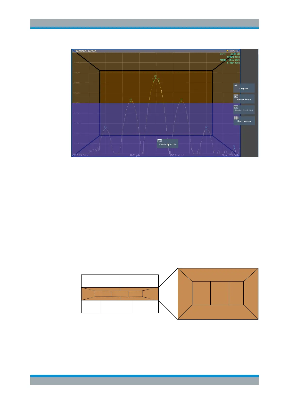
Figure 5-28: Moving a window in SmartGrid mode
The brown area indicates the possible "drop area" for the window, i.e. the area in which
the window can be placed. A blue area indicates the (approximate) layout of the win-
dow as it would be if the icon were dropped at the current position. The frames indicate
the possible destinations of the new window with respect to the existing windows:
above/below, right/left or replacement (as illustrated in Figure 5-29). If an existing win-
dow would be replaced, the drop area is highlighted in a darker color shade.
Positioning the window
The screen can be divided into up to four rows. Each row can be split into up to four
columns, where each row can have a different number of columns. However, rows
always span the entire width of the screen and may not be interrupted by a column. A
single row is available as the drop area for the window in the SmartGrid. The row can
be split into columns, or a new row can be inserted above or below the existing row (if
the maximum of 4 has not yet been reached).
1
1
2 223 3
A
B
C
Figure 5-29: SmartGrid window positions
1 = Insert row above or below the existing row
2 = Create a new column in the existing row
3 = Replace a window in the existing row
Operating the Instrument

 Loading...


