Measurements and Results
R&S
®
FSW
144User Manual 1173.9411.02 ─ 43
7.1.5.2 Measuring the Modulation Depth of an AM-Modulated Carrier in the Frequency
Domain
In the frequency range display, the AM side bands can be resolved with a narrow
bandwidth and measured separately. The modulation depth of a carrier modulated with
a sinusoidal signal can then be measured. Since the dynamic range of a signal ana-
lyzer is very large, extremely small modulation depths can also be measured precisely.
For this purpose, the R&S FSW provides measurement routines that output the modu-
lation depth numerically in percent directly.
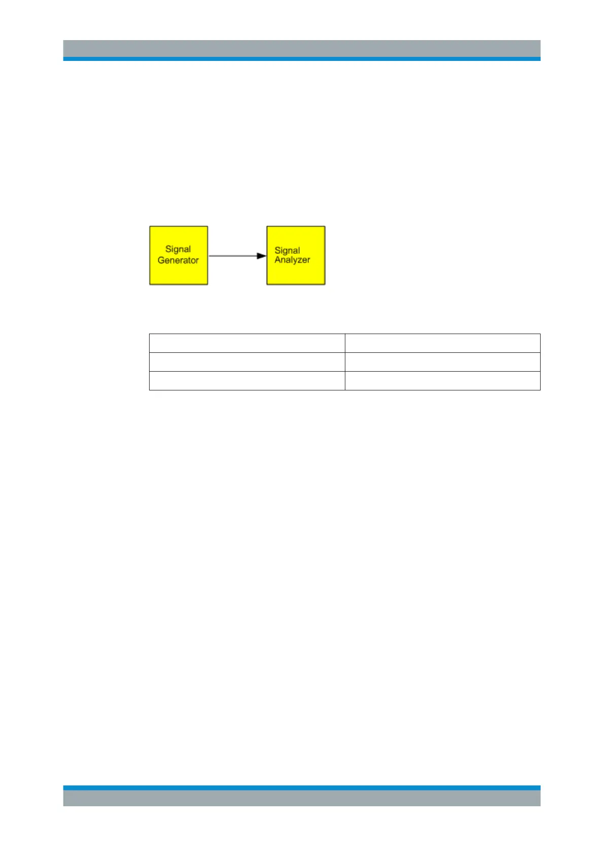
Figure 7-9: Test setup
Table 7-4: Signal generator settings (e.g. R&S SMW)
Frequency 128 MHz
Level -30 dBm
Modulation 50 % AM, 10 kHz AF
1. Select [PRESET] to reset the instrument.
2. Set the center frequency to 128
MHz.
3. Set the frequency span to 50
kHz.
4. Select [MEAS] > "AM Modulation Depth" to activate the modulation depth mea-
surement.
The R&S FSW automatically sets a marker to the carrier signal in the center of the
diagram and one delta marker each to the upper and lower AM sidebands. The
R&S FSW calculates the AM modulation depth from the level differences of the
delta markers to the main marker and outputs the numeric value in the marker
information.
Basic Measurements

 Loading...


