Measurements and Results
R&S
®
FSW
145User Manual 1173.9411.02 ─ 43
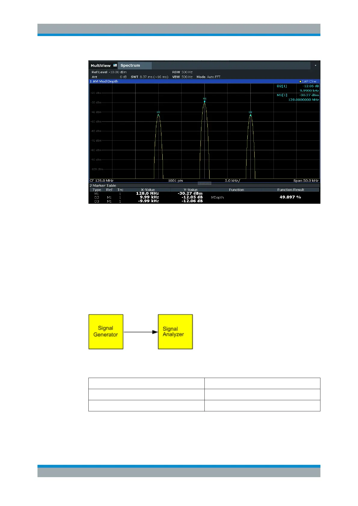
Figure 7-10: Measurement of the AM modulation depth
The modulation depth is displayed as "MDepth". The frequency of the AF signal can be
obtained from the frequency display of the delta marker.
7.1.5.3 Measuring AM-Modulated Signals
The R&S FSW rectifies the RF input signal (that is, removes the negative parts) and
displays it as a magnitude spectrum. The rectification also demodulates AM-modulated
signals. The AF voltage can be displayed in zero span if the modulation sidebands fall
within the resolution bandwidth.
Displaying the AF of an AM-modulated signal (Zero Span)
Figure 7-11: Test setup
Table 7-5: Signal generator settings (e.g. R&S SMW)
Frequency 128 MHz
Level -30 dBm
Modulation 50 % AM, 1 kHz AF
1. Select [PRESET] to reset the instrument.
2. Set the center frequency to 128
MHz.
Basic Measurements

 Loading...


