Measurements and Results
R&S
®
FSW
163User Manual 1173.9411.02 ─ 43
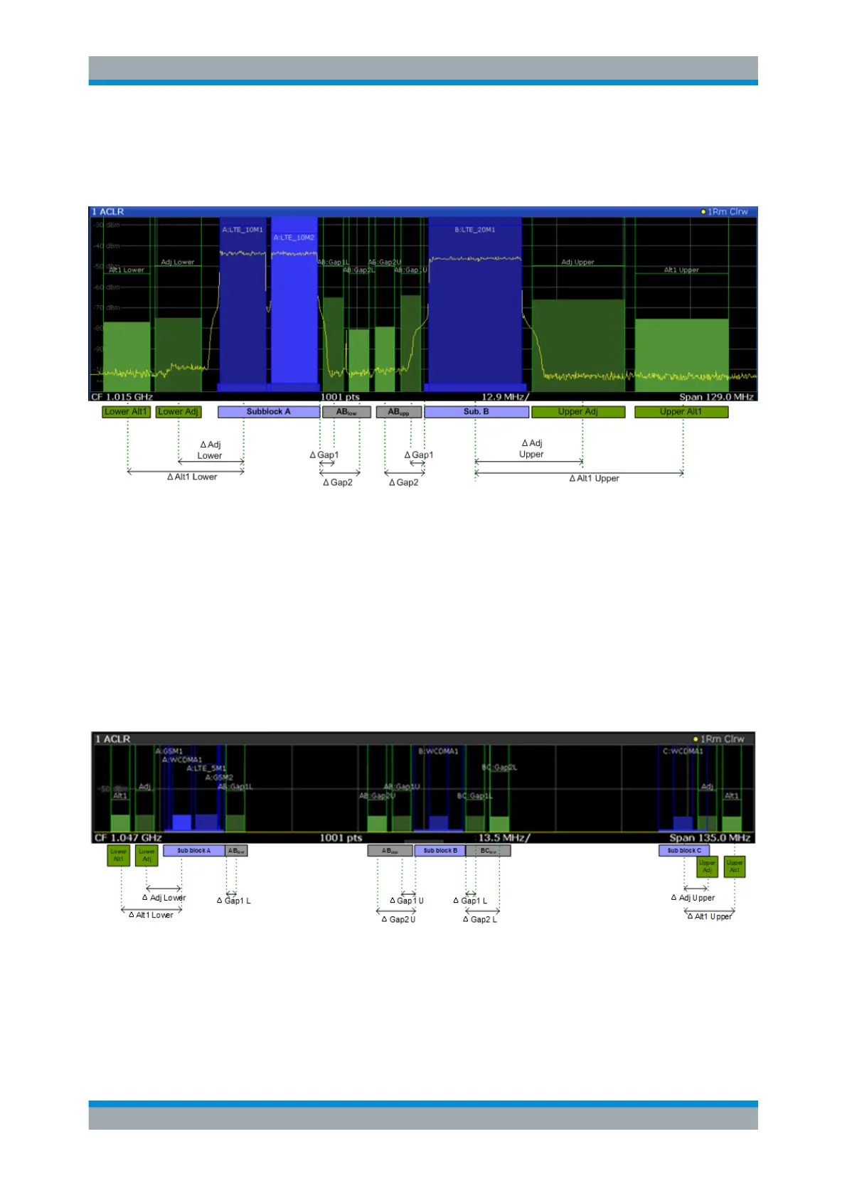
those in the lower gap, but inverted. To either side of the outermost transmit channels,
lower and upper adjacent channels can be defined as in common ACLR measurement
setups.
Figure 7-24: MSR signal structure
Asymmetrical gap channels
Gap channels between sub blocks can now also be asymmetrical, that is: channels in
the lower and upper gaps are not identical. For example, in Figure 7-25, the gap
between sub blocks A and B contains one lower channel (AB:Gap1L), but two upper
channels (AB:Gap1U, AB:Gap2U). Furthermore, the gaps between different sub blocks
need not be identical. For example, the gap between sub blocks A and B contains 3
gap channels, while the gap between sub blocks B and C contains only two gap chan-
nels (BC:Gap1L, BC:Gap2L, which are not identical to the lower gap channels in gap
AB.
Figure 7-25: Asymmetrical MSR signal structure
Sub block and channel definition
The sub blocks are defined by a specified center frequency, RF bandwidth, and num-
ber of transmit channels.
Channel Power and Adjacent-Channel Power (ACLR) Measurement

 Loading...


