Measurements and Results
R&S
®
FSW
223User Manual 1173.9411.02 ─ 43
The R&S FSW noise power ratio measurement allows you to specify your satellite
channel and up to 25 notch filters in your measurement setup. For a more general
measurement, the bandwidth on which the total power density is based can be
selected freely.
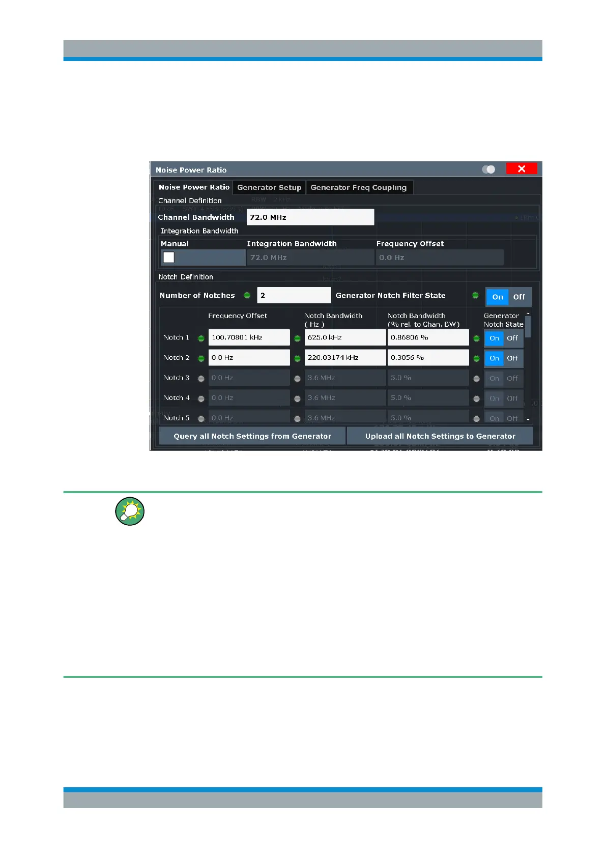
Figure 7-41: Noise Power Ratio configuration dialog with a signal generator connected
An LED next to a setting indicates whether the setting was adjusted on the connected
generator successfully. They are only available if a valid generator IP address is detec-
ted (see "Signal Generator IP Address" on page 228).
The LED indicates the following states:
●
green: setting on the R&S FSW is valid and was successfully applied on the signal
generator
●
red: control error, for example because the specified value cannot be applied on
the signal generator
●
gray: signal generator control off
Note that if you change the setting on the generator manually, the analyzer does not
adapt the setting automatically. The green LED for a previous successful transmission
does not change.
Channel Bandwidth.....................................................................................................224
Integration Bandwidth................................................................................................. 224
Number of Notches..................................................................................................... 224
Generator Notch Filter State....................................................................................... 224
Frequency Offset per Notch........................................................................................225
Noise Power Ratio (NPR) Measurement

 Loading...


