Common Measurement Settings
R&S
®
FSW
384User Manual 1173.9411.02 ─ 43
can be carried out to compensate for the effects of the test setup (e.g. frequency
response of connecting cables).
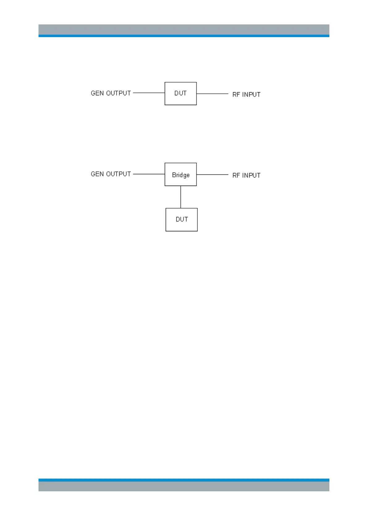
Figure 8-6: Test setup for transmission measurement
Reflection Measurement
Scalar reflection measurements can be carried out using a reflection-coefficient mea-
surement bridge.
Figure 8-7: Test setup for reflection measurement
Generated signal input
In order to use the functions of the external generator, an appropriate generator must
be connected and configured correctly. In particular, the generator output must be con-
nected to the RF input of the R&S FSW.
External reference frequency
In order to enhance measurement accuracy, a common reference frequency should be
used for both the R&S FSW and the generator. If no independent 10 MHz reference
frequency is available, it is recommended that you connect the reference output of the
generator with the reference input of the R&S FSW and that you enable usage of the
external reference on the R&S FSW via "SETUP" > "Reference" > "External Refer-
ence".
For more information on external references see Chapter 12.5, "Reference Frequency
Settings", on page 699.
Connection errors
If no external generator is connected, if the connection address is not correct, or the
generator is not ready for operation, an error message is displayed (e.g."Ext. Genera-
tor TCPIP Handshake Error!", see "Displayed Information and Errors" on page 392).
Data Input and Output

 Loading...


