Common Measurement Settings
R&S
®
FSW
405User Manual 1173.9411.02 ─ 43
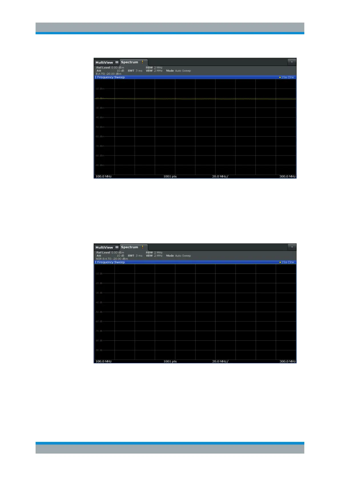
Figure 8-8: Measurement results from generator, analyzer and connecting cables
13. Select "Source Calibration Normalize": "On" to set the measurement results for the
current setup to 0, thus eliminating all effects from the generator, the analyzer and
the connecting cables from subsequent measurements with the band elimination
filter.
The reference line is displayed at 0 dB at the top of the diagram (100%).
Figure 8-9: Normalized measurement results after calibration
Measuring the effects of the DUT
After calibration we can insert the band elimination filter (our DUT) in the measurement
setup.
1. Connect the signal generator output to the band elimination filter.
Data Input and Output

 Loading...


