Common Measurement Settings
R&S
®
FSW
406User Manual 1173.9411.02 ─ 43
2. Connect the band elimination filter output to the [RF input] connector of the
R&S FSW.
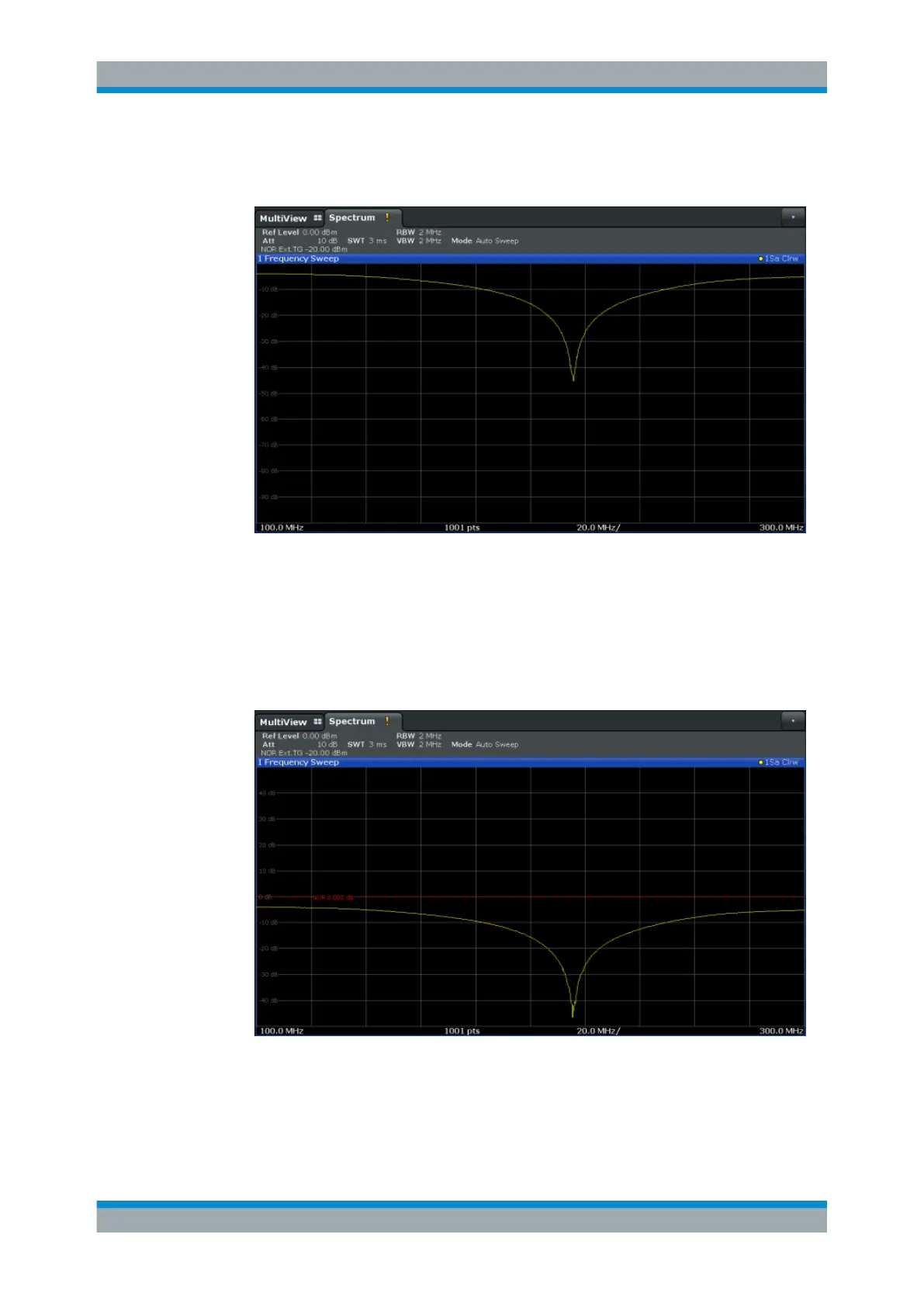
Figure 8-10: Band elimination filter results
3. Shift the reference line from the top of the diagram to the middle of the diagram by
changing the position of the reference point 0.0
dB to 50
%.
In the "Source Calibration" tab, enter "Position": 50
%.
At the same time, the range of the displayed y-axis moves from [-100.0
dB to 0
dB]
to [-50
dB to +50
dB].
Figure 8-11: Reference line shifted to middle of diagram (50%)
Data Input and Output

 Loading...


