Common Measurement Settings
R&S
®
FSW
407User Manual 1173.9411.02 ─ 43
Compensating the effects of additional attenuation after calibration
After calibration, an additional attenuator is inserted between the DUT and the
R&S FSW. This may be necessary, for example, to protect the analyzer's input connec-
tor. Nevertheless, we are only interested in the effects of the DUT, not those of the
additional protective attenuator. Thus, we will compensate these effects in the result
display on the R&S FSW by moving the reference line.
1. Connect a 3 dB attenuator between the band elimination filter output and the [RF
input] connector on the R&S FSW.
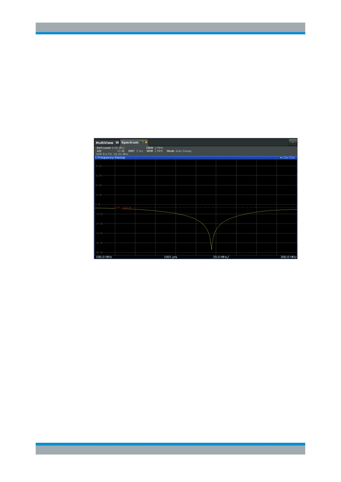
The measurement results are now 3 dB lower.
Figure 8-12: Measurement results with additional attenuator
2. In the "Source Calibration" tab, enter "Reference Value":-3
dB.
The reference line is shifted down by 3 dB so that the measurement trace is dis-
played on the reference line again.
At the same time, the scaling of the y-axis is changed: -3 dB are now shown at
50% of the diagram; the range is [-53
dB to +47
dB].
Data Input and Output

 Loading...


