Common Measurement Settings
R&S
®
FSW
415User Manual 1173.9411.02 ─ 43
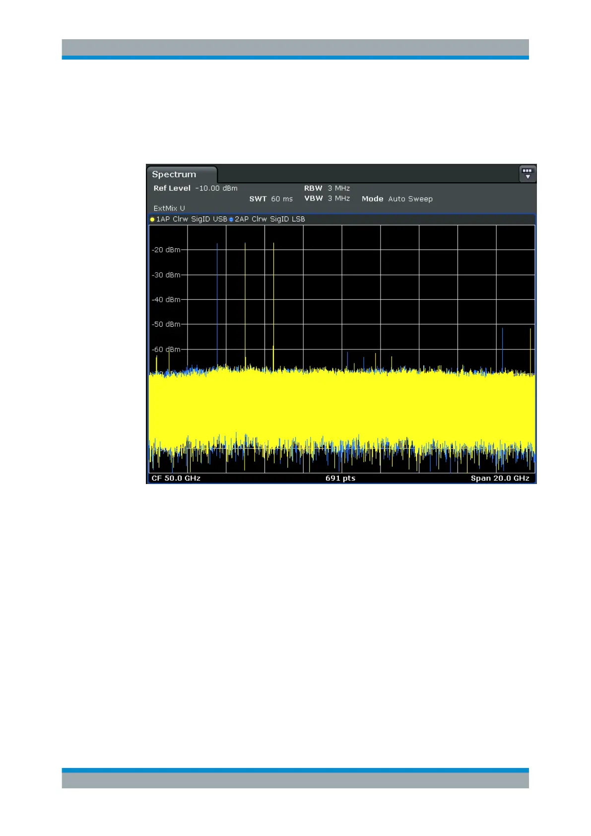
Signal ID function
Two sweeps are performed alternately. Trace 1 shows the trace measured on the
upper side band (USB) of the LO (the test sweep), trace 2 shows the trace measured
on the lower side band (LSB), i.e. the reference sweep.
Figure 8-17: Signal identification function (Signal ID) with optional external mixer
The reference sweep is performed using an LO setting shifted downwards by 2*IF/
<Harmonic order>. Input signals in the desired sideband that are converted using the
specified harmonic are displayed in both traces at the same position on the frequency
axis. Image signals and mixer products caused by other harmonics are displayed at
different positions in both traces. The user identifies the signals visually by comparing
the two traces.
Since the LO frequency is displaced downwards in the reference sweep, the conver-
sion loss of the mixer may differ from the test sweep. Therefore the signal level should
only be measured in the test sweep (trace 1).
Auto ID function
The Auto ID function basically functions like Signal ID function. However, the test and
reference sweeps are converted into a single trace by a comparison of maximum peak
values of each sweep point. The result of this comparison is displayed in trace 3 if "Sig-
nal ID" is active at the same time. If "Signal ID" is not active, the result can be dis-
Data Input and Output

 Loading...


