Common Measurement Settings
R&S
®
FSW
452User Manual 1173.9411.02 ─ 43
Reference Level..........................................................................................................452
└ Shifting the Display (Offset).......................................................................... 453
└ Unit................................................................................................................453
└ Setting the Reference Level Automatically (Auto Level)...............................454
RF Attenuation............................................................................................................ 454
└ Attenuation Mode / Value..............................................................................454
Using Electronic Attenuation.......................................................................................454
Input Settings.............................................................................................................. 455
└ Preamplifier...................................................................................................455
└ Ext. PA Correction.........................................................................................455
Noise Cancellation...................................................................................................... 456
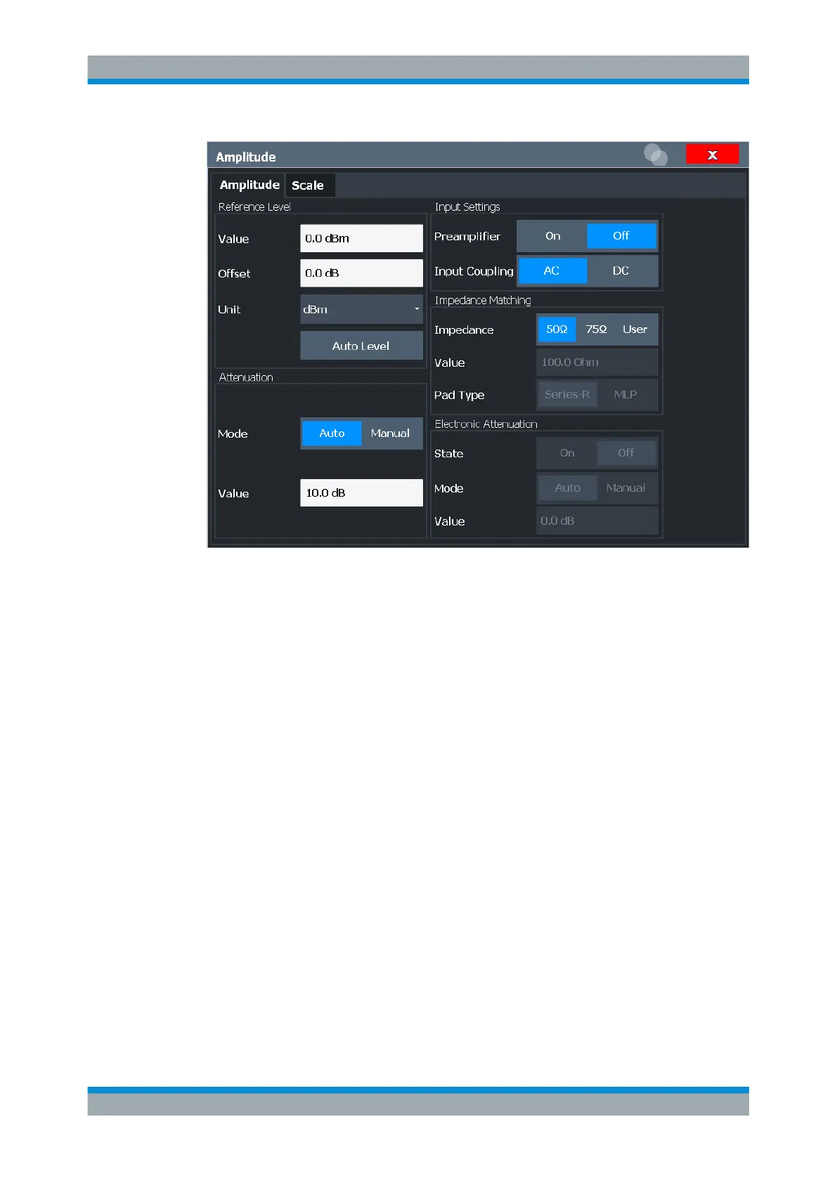
Reference Level
Defines the expected maximum input signal level. Signal levels above this value may
not be measured correctly, which is indicated by the "IF Overload" status display
("OVLD" for analog baseband or digital baseband input).
The reference level can also be used to scale power diagrams; the reference level is
then used as the maximum on the y-axis.
Since the hardware of the R&S FSW is adapted according to this value, it is recom-
mended that you set the reference level close above the expected maximum signal
level. Thus you ensure an optimum measurement (no compression, good signal-to-
noise ratio).
For details, see Chapter 8.4.1.1, "Reference Level", on page 449.
Note that for input from the External Mixer (R&S FSW-B21) the maximum reference
level also depends on the conversion loss, see "Reference level" on page 413.
Amplitude and Vertical Axis Configuration
 Loading...


