Getting Started
R&S
®
FSW
54User Manual 1173.9411.02 ─ 43
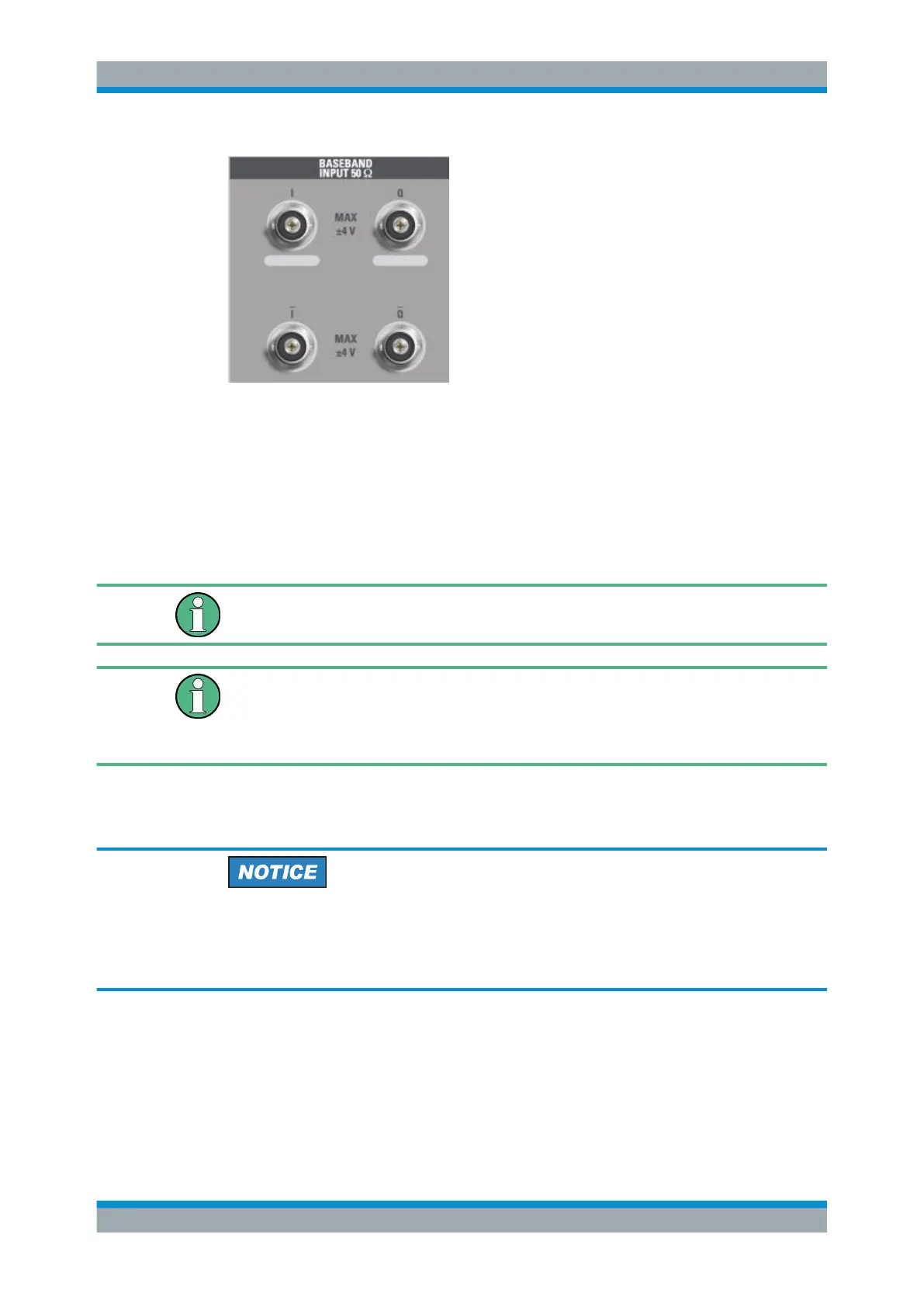
The upper BNC connectors BASEBAND INPUT I and BASEBAND INPUT Q are used
to input:
●
Single-ended signals
●
The positive signal input for differential signals
●
Input from active Rohde & Schwarz probes (see data sheet)
The lower BNC connectors Ī and Ǭ are used to input the negative signal for differential
signals.
R&S FSW85
The R&S FSW85 provides only two connectors; differential input is not supported.
Complex signal input (I+jQ)
For complex signal input (I+jQ), always use two identical cables for the I and Q con-
nectors (same length, same type, same manufacturer). Otherwise, time delay or gain
imbalance can occur between the different cables, which cannot be calibrated.
All connectors have a fixed impedance of 50 Ω and can receive a maximum input level
of 4 V
pp
each.
Risk of instrument damage
Do not overload the BASEBAND INPUT connectors. An input voltage of 4 V must
never be exceeded. Noncompliance destroys the Analog Baseband Interface compo-
nents.
The device that provides analog baseband input (or the probe) must be connected to
the R&S FSW accordingly.
Since the Digital I/Q input and the Analog Baseband input use the same digital signal
path, both cannot be used simultaneously. When one is activated, established connec-
tions for the other are disconnected. When the second input is deactivated, connec-
Instrument Tour

 Loading...


